双光子成像和近红外二区荧光共聚焦成像/树状大分子CT/MRI双模态成像造影剂/锰螯合物磁共振成像(MRI)
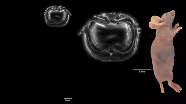
我们使用 PTD 纳米颗粒实现了透过老鼠头骨脑血管的三维高分辨(分辨率 25.4 微米),高信号/背景比例( 22.3 dB)成像. 其成像深度高达 1001 微米. 该脑血管光声成像效果比较近报道的双光子成像和近红外二区荧光共聚焦成像的效果好.

▲Figure 2. PA imaging of subcutaneous HepG2 tumor-bearing mouse ear with a colorbar 0.06-1. (a) Photo of mouse ear bearing subcutaneous tumor for PA imaging. Representative xy projected tumor bearing mouse ear image (7.00 × 7.00 mm, x × y) before (b) and after (c) PTD NP administration. (d) Depth-encoded maximum amplitude projection image corresponding to Figure c (The PA signal color changes correspond to different depths according to the color chart for depth information on the right side). (e) and (f) 3D reconstruction of tumor-bearing mouse ear vasculature images from different view side (7.00 × 7.00 × 0.76 mm, x × y × z) and the tumor margin was labelled with white-dashed circle. (g) Layer-by-layer PA images (7.00 × 7.00 mm, x × y) of subcutaneous tumor-bearing mouse ear with white-dashed circle for labelling tumor margin in each layer. (h) and (i) The PA intensity profile (black curve) along the green line in the zoomed area (insets, Figures h and i) which represents the area labelled with green-dashed circle at depths of 370 and 755 µm, respectively. The Gaussian fits to the profiles are presented using red curves. Gaussian-fitted full width at half maximum (FWHM) of the vessel along the green line is presented at different depth.
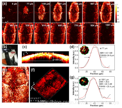
▲Figure 3. In vivo ORPAMI of whole-cortex brain through intact skull after administration of PTD NPs through tail-vain (colorbar: 0.06-1). (a) Layer-by-layer PA images (8 × 6 mm, x × y) of mouse brain. The deepest area reached 1001 µm. (b) Photo of mouse for imaging. (c) Representative xz projected brain vasculature image (8 × 1 mm, x × z). (e) Representative xy projected brain vasculature image (8 × 6 mm, x × y). (f) 3D reconstruction of brain vasculature (8 × 6 × 1 mm, x × y × z). (d) and (g) The PA intensity profiles along the green line in the zoomed area (inset, Figure d and g) which represents the area labelled with green-dashed circle (Figure a) at the depths of 77 and 1001 µm, respectively. The Gaussian fits to the profile are shown in red curve. Gaussian-fitted full width at half maximum (FWHM) of the vessel along the green line is presented at different depth.
总结与展望
实现了体外造影剂辅助近红外二区光声显微成像. 微流控技术制备共轭高分子, 可以实现尺寸可控, 形貌均一. 同时,共轭高分子生物相容性好,吸光系数大,光声稳定性好,是很好的活体成像的光声造影剂. 我们证明二区共轭高分子辅助光声显微成像可以准确勾画肿瘤边界, 解析肿瘤内部和周围正常组织血管结构, 准确成像脑补三维复杂血管脉络. 因此, 共轭高分子纳米颗粒是很有潜力的活体成像造影剂, 用来理解生理和病理过程。
T2对比剂(顺磁性铁锰)
普鲁士蓝纳米颗粒
普鲁士蓝纳米颗粒;纯水溶液;粒径:100nm
亲和素表面磁性氧化铁微球(1um)
1um亲和素包裹的磁性四氧化三铁微球;纯水溶液;粒径:1±0.1um
羧基表面磁性氧化铁微球(1um)
1um羧基化磁微球;纯水溶液;粒径:1±0.1um
磁性氧化铁纳米球(500nm)
500nm磁性氧化铁纳米球;纯水溶液;粒径:300±50nm
磁性氧化铁纳米球(300nm)
300nm磁性氧化铁纳米球;纯水溶液;粒径:300±50nm
磁性氧化铁纳米球(200nm)
200nm磁性氧化铁纳米球;纯水溶液;粒径:200±50nm
PEG化磁性锰锌铁氧体纳米晶(氨基)
PEG化磁性锰锌铁氧体纳米晶(-NH2);纯水溶液;粒径:10±5nm
PEG化磁性锰锌铁氧体纳米晶(羧基)
PEG化磁性锰锌铁氧体纳米晶(-COOH);纯水溶液;粒径:10±5nm
PEG化磁性锰锌铁氧体纳米晶(甲氧基)
PEG化磁性锰锌铁氧体纳米晶(-OCH3);纯水溶液;粒径:10±5nm
锰锌铁氧体纳米晶
锰锌铁氧体纳米晶(高温热解法);氯仿溶液;粒径:25±5nm
荧光素标记Fe3O4颗粒;USPIO;SA-DSPE-PEG-Fe3O4
荧光素修饰的四氧化三铁磁性纳米颗粒(FITC-Fe3O4);纯水溶液;粒径:10±5nm
亲和素表面Fe3O4颗粒SA-DSPE-PEG-Fe3O4;10nm
链霉亲和素修饰的四氧化三铁磁性纳米颗粒(SA-Fe3O4);纯水溶液;粒径:10±5nm
氨基端PEG化Fe3O4颗粒;DSPE-PEG-Fe3O4(-NH2);10nm
PEG化四氧化三铁磁性纳米颗粒(-NH2);纯水溶液;粒径:10±5nm
羧基端PEG化Fe3O4颗粒;DSPE-PEG-Fe3O4(-COOH);10nm
PEG化四氧化三铁磁性纳米颗粒(-COOH);纯水溶液;粒径:10±5nm
甲氧基PEG化Fe3O4颗粒;DSPE-PEG-Fe3O4(-CH3O);50nm
PEG化四氧化三铁磁性纳米颗粒(-OCH3);氯仿溶液;粒径:50±5nm
PEG化Fe3O4颗粒;25nm;PEG-Fe3O4
PEG化四氧化三铁磁性纳米颗粒(-OCH3);纯水溶液;粒径:25±5nm
PEG化Fe3O4颗粒;PEG-USPIO;10nm
PEG化四氧化三铁磁性纳米颗粒(-OCH3);纯水溶液;粒径:10±5nm
油酸表面Fe3O4颗粒氯仿溶液;OA-Fe3O4-C
油酸修饰的四氧化三铁磁性纳米颗粒(OA-Fe3O4,高温热解法);氯仿溶液;粒径:10±5nm
油酸表面Fe3O4颗粒粉末;OA-USPIO
油酸修饰的四氧化三铁磁性纳米颗粒(OA-Fe3O4,高温热解法);固体粉末;粒径:10±5nm
wyf 04.01