防火墙(Firewall)也称防护墙,是由Check Point创立者Gil Shwed于1993年发明并引入国际互联网(US5606668(A)1993-12-15)防火墙是位于内部网和外部网之间的屏障,它按照系统管理员预先定义好的规则来控制数据包的进出。防火墙是系统的第一道防线,其作用是防止非法用户的进入。
今天给大家带来的是华为防火墙相关的实战,内容详实,可供参考!
目录
目录
初始化防火墙
初始化防火墙:
开启Web管理界面:
配置Console口登陆:
配置telnet密码认证:
配置telnet用户名密码认证:
常用查询命令:
防火墙基本配置
初始化防火墙:
配置内网接口:
配置外网接口:
配置安全策略:
配置源NAT:
配置目标NAT:
NAT 地址转换
配置内网区域:
配置外网区域:
配置源NAT:
配置目标NAT:
配置交换机
配置两台交换机:
配置防火墙:
添加防火墙区域:
主备双机热备
放行所有数据包(两台墙):
配置IP地址(两台) 给防火墙的两个接口配置好IP地址.
开启源NAT地址:
开启VRRP支持(两台)
HRP配置(两台):
检查配置:
配置负载均衡
配置防火墙接口:
加入相应的区域内:
放行数据包:
配置负载均衡:
初始化防火墙
初始化防火墙:
默认用户名为admin,默认的密码Admin@123,这里修改密码为wljsghq@163.
Username:admin
Password:*****
The password needs to be changed. Change now? [Y/N]: y
Please enter old password: Admin@123
Please enter new password: LyShark@163
Please confirm new password: LyShark@163<FW1> system-view                      // 进入系统视图
[FW1] sysname FW1                      // 给防火墙命名
[FW1] undo info-center enable          // 关闭日志弹出功能
[FW1] quit
<FW1> language-mode Chinese            // 将提示修改为中文
Change language mode, confirm? [Y/N] y提示:改变语言模式成功.
开启Web管理界面:
默认防火墙console接口IP地址是192.168.0.1.
<FW1> system-view
[FW1] web-manager enable                                // 开启图形管理界面
[FW1] interface GigabitEthernet 0/0/0
[FW1-GigabitEthernet0/0/0] ip address 192.168.0.1 24    // 给接口配置IP地址
[FW1-GigabitEthernet0/0/0] service-manage all permit    // 放行该端口的请求
[FW1-GigabitEthernet0/0/0] display this
配置Console口登陆:
<FW1> system-view                                               // 进入系统视图
[FW1] user-interface console 0                                  // 进入console0的用户配置接口
[FW1-ui-console0] authentication-mode password                  // 使用密码验证模式
[FW1-ui-console0] set authentication password cipher Admin1234  // 设置密码为Admin1234
[FW1-ui-console0] quit                                          // 退出用户配置接口
配置telnet密码认证:
配置密码认证模式,此处配置密码为Admin@123.
<FW1> system-view[FW1] telnet server enable                              // 开启Telnet支持
[FW1] interface GigabitEthernet 0/0/0                   // 选择配置接口
[FW1-GigabitEthernet0/0/0] service-manage telnet permit // 允许telnet
[FW1-GigabitEthernet0/0/0] quit[FW1] user-interface vty 0 4                                  // 开启虚拟终端
[FW1-ui-vty0-4] protocol inbound telnet                       // 允许telnet
[FW1-ui-vty0-4] authentication-mode password                  // 设置为密码认证模式
[FW1-ui-vty0-4] set authentication password cipher Admin@123  // 设置用户密码[USG6000V1] firewall zone trust                                // 选择安全区域
[USG6000V1-zone-trust] add interface GE0/0/0                   // 添加到安全区域
配置telnet用户名密码认证:
<FW1> system-view                                       // 进入系统视图
[FW1] interface GigabitEthernet 0/0/0                   // 进入接口配置
[FW1-GigabitEthernet0/0/0] ip address 192.168.0.1 24    // 配置接口IP
[FW1-GigabitEthernet0/0/0] service-manage telnet permit // 允许telnet
[FW1-GigabitEthernet0/0/0] service-manage ping permit   // 允许ping
[FW1-GigabitEthernet0/0/0] quit                         //退出[FW1] firewall zone trust                              // 进入trust安全域配置
[FW1-zone-trust] add interface GigabitEthernet 0/0/0   // 把GE0/0/0加入到trust安全域
[FW1-zone-trust] quit[FW1] telnet server enable                // 启用telnet服务
[FW1] user-interface vty 0 4              // 进入vty0-4的用户配置接口
[FW1-ui-vty0-4] authentication-mode aaa   // 使用AAA验证模式
[FW1-ui-vty0-4] user privilege level 3    // 配置用户访问的命令级别为3
[FW1-ui-vty0-4] protocol inbound telnet   // 配置telnet
[FW1-ui-vty0-4] quit                      // 退出用户配置接口[FW1] aaa                                 // 进入AAA配置视图
[FW1-aaa] manager-user lyshark            // 创建用户vtyadmin
[FW1-aaa-manager-user-lyshark] password cipher admin@123   // 配置用户密码
[FW1-aaa-manager-user-lyshark] service-type telnet         // 配置服务类型
[FW1-aaa-manager-user-lyshark] quit                        // 退出[FW1-aaa] bind manager-user lyshark role system-admin     // 绑定管理员角色
[FW1-aaa] quit                                             // 退出AAA视图
常用查询命令:
查询防火墙的其他配置,常用的几个命令如下.
[FW1] display ip interface brief            // 查默认接口信息
[FW1] display ip routing-table              // 显示路由表
[FW1] display zone                          // 显示防火墙区域
[FW1] display firewall session table        // 显示当前会话
[FW1] display security-policy rule all      // 显示安全策略
配置到这里,我们就可以在浏览器中访问了,其访问地址是http://192.168.0.1
防火墙基本配置

初始化防火墙:
初始化配置,并设置好防火墙密码,此处用户名admin密码是wljsghq@123.
Username:admin
Password:*****
The password needs to be changed. Change now? [Y/N]: y
Please enter old password: Admin@123
Please enter new password: Lyshark@163
Please confirm new password: Lyshark@163<USG6000V1> system-view                                 // 进入系统视图
[USG6000V1] sysname FW1                                 // 给防火墙命名
[FW1] undo info-center enable                           // 关闭日志弹出功能
[FW1] quit
<FW1> language-mode Chinese                             // 将提示修改为中文
[FW1] web-manager enable                                // 开启图形管理界面
[FW1] interface GigabitEthernet 0/0/0
[FW1-GigabitEthernet0/0/0] service-manage all permit    // 放行该端口的请求
配置内网接口:
配置内网的接口信息,这里包括个GE 1/0/0 and GE 1/0/1这两个内网地址.
<FW1> system-view
[FW1] interface GigabitEthernet 1/0/0
[FW1-GigabitEthernet1/0/0] ip address 192.168.1.1 255.255.255.0
[FW1-GigabitEthernet1/0/0] undo shutdown
[FW1-GigabitEthernet1/0/0] quit[FW1] interface GigabitEthernet 1/0/1
[FW1-GigabitEthernet1/0/1] ip address 192.168.2.1 255.255.255.0
[FW1-GigabitEthernet1/0/1] undo shutdown
[FW1-GigabitEthernet1/0/1] quit# -------------------------------------------------------
[FW1] firewall zone trust                                       // 将前两个接口加入trust区域
[FW1-zone-trust] add interface GigabitEthernet  1/0/0
[FW1-zone-trust] add interface GigabitEthernet  1/0/1
配置外网接口:
配置外网接口GE 1/0/2接口的IP地址,并将其加入到untrust区域中.
[FW1] interface GigabitEthernet 1/0/2                            // 选择外网接口
[FW1-GigabitEthernet1/0/2] undo shutdown                         // 开启外网接口
[FW1-GigabitEthernet1/0/2] ip address 10.10.10.10 255.255.255.0  // 配置IP地址
[FW1-GigabitEthernet1/0/2] gateway 10.10.10.20                   // 配置网关
[FW1-GigabitEthernet1/0/2] undo service-manage enable
[FW1-GigabitEthernet1/0/2] quit# -------------------------------------------------------
[FW1] firewall zone untrust                                      // 选择外网区域
[FW1-zone-untrust] add interface GigabitEthernet 1/0/2           // 将接口加入到此区域
配置安全策略:
配置防火墙安全策略,放行trust(内网)-->untrust(外网)的数据包.
[FW1] security-policy                                         // 配置安全策略
[FW1-policy-security] rule name lyshark                       // 规则名称
[FW1-policy-security-rule-lyshark] source-zone trust          // 原安全区域(内部)
[FW1-policy-security-rule-lyshark] destination-zone untrust   // 目标安全区域(外部)[FW1-policy-security-rule-lyshark] source-address any         // 原地址区域
[FW1-policy-security-rule-lyshark] destination-address any    // 目标地址区域
[FW1-policy-security-rule-lyshark] service any                // 放行所有服务
[FW1-policy-security-rule-lyshark] action permit              // 放行配置
[FW1-policy-security-rule-lyshark] quit
配置源NAT:
配置原NAT地址转换,仅配置源地址访问内网 --> 公网的转换.
[FW1] nat-policy                                                      // 配置NAT地址转换
[FW1-policy-nat] rule name lyshark                                    // 指定策略名称
[FW1-policy-nat-rule-lyshark] egress-interface GigabitEthernet 1/0/2  // 外网接口IP
[FW1-policy-nat-rule-lyshark] action source-nat easy-ip               // 源地址转换
[FW1-policy-nat-rule-lyshark] display this
配置目标NAT:
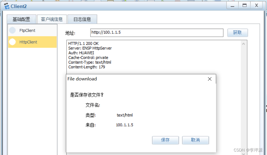
外网访问10.10.10.10自动映射到内网的192.168.2.1这台主机上.
[FW1] firewall zone untrust                                      // 选择外网区域
[FW1-zone-untrust] add interface GigabitEthernet 1/0/2           // 将接口加入到此区域# ----NAT规则---------------------------------------------------
# 外网主机访问10.10.10.10主机自动映射到内部的192.168.2.2
[FW1] firewall detect ftp
[FW1] nat server lyshark global 10.10.10.10 inside 192.168.2.2 no-reverse# ----放行规则---------------------------------------------------
[FW1] security-policy                                         // 配置安全策略
[FW1-policy-security] rule name untrs-trs                     // 规则名称
[FW1-policy-security-rule-lyshark] source-zone untrust        // 原安全区域(外部)
[FW1-policy-security-rule-lyshark] destination-zone trust     // 目标安全区域(内部)
[FW1-policy-security-rule-lyshark] action permit              // 放行配置
[FW1-policy-security-rule-lyshark] quit
NAT 地址转换

配置内网区域:
分别配置防火墙内网接口GE1/0/0 and GE1/0/1设置IP地址,并加入指定区域内.
<FW1>system-view
[FW1]undo info-center enable# ----配置IP地址-----------------------------------------------
[FW1] interface GigabitEthernet 1/0/0
[FW1-GigabitEthernet1/0/0] ip address 192.168.1.1 24
[FW1-GigabitEthernet1/0/0] quit
[FW1] interface GigabitEthernet 1/0/1
[FW1-GigabitEthernet1/0/1] ip address 192.168.2.1 24
[FW1-GigabitEthernet1/0/1] quit# ----加入到指定区域--------------------------------------------
[FW1] firewall zone trust
[FW1-zone-trust] add interface GigabitEthernet 1/0/0[FW1] firewall zone dmz
[FW1-zone-dmz] add interface GigabitEthernet 1/0/1
配置外网区域:
然后配置外网地址,将Gig 1/0/2加入到untrust区域内.
[FW1] interface GigabitEthernet 1/0/2
[FW1-GigabitEthernet1/0/2] ip address 10.10.10.10 8[FW1] firewall zone untrust
[FW1-zone-dmz] add interface GigabitEthernet 1/0/2
配置源NAT:
配置原NAT地址转换,仅配置源地址访问内网 --> 公网的转换.
# ----配置源NAT转换---------------------------------------------
[FW1] nat-policy                                                      // 配置NAT地址转换
[FW1-policy-nat] rule name lyshark                                    // 指定策略名称
[FW1-policy-nat-rule-lyshark] egress-interface GigabitEthernet 1/0/2  // 外网接口IP
[FW1-policy-nat-rule-lyshark] action source-nat easy-ip               // 源地址转换
[FW1-policy-nat-rule-lyshark] display this# ----放行相关安全策略------------------------------------------
[FW1] security-policy
[FW1-policy-security] rule name trust_untrust
[FW1-policy-security-rule] source-zone trust
[FW1-policy-security-rule] destination-zone untrust
[FW1-policy-security-rule] action permit
配置目标NAT:
外网访问10.10.10.10自动映射到内网的192.168.2.2这台主机上.
# ----NAT规则---------------------------------------------------
# 外网主机访问10.10.10.10主机自动映射到内部的192.168.2.2
[FW1] firewall detect ftp
[FW1]nat server lyshark global 10.10.10.10 inside 192.168.2.2 no-reverse # ----放行规则---------------------------------------------------
[FW1] security-policy                                           // 配置安全策略
[FW1-policy-security] rule name untrs-DMZ                       // 规则名称
[FW1-policy-security-rule-untrs-DMZ] source-zone untrust        // 原安全区域(外部)
[FW1-policy-security-rule-untrs-DMZ] destination-zone trust     // 目标安全区域(内部)
[FW1-policy-security-rule-untrs-DMZ] destination-address 192.168.2.2 24
[FW1-policy-security-rule-untrs-DMZ] service any
[FW1-policy-security-rule-untrs-DMZ] action permit              // 放行配置
[FW1-policy-security-rule-untrs-DMZ] quit
配置交换机

配置两台交换机:
分别配置两台交换机,并划分到相应的VLAN区域内.
# ----配置LSW1交换机--------------------------------------------
<Huawei> system-view
[LSW1] vlan 10                                     // 创建VLAN10
[LSW1] quit
[LSW1] interface Ethernet 0/0/1                    // 将该接口配置为trunk
[LSW1-Ethernet0/0/1] port link-type trunk
[LSW1-Ethernet0/0/1] port trunk allow-pass vlan 10 // 加入到vlan 10
[LSW1-Ethernet0/0/1] quit[LSW1] port-group group-member Eth0/0/2 to Eth0/0/3
[LSW1-port-group] port link-type access
[LSW1-port-group] port default vlan 10
[LSW1-port-group] quit# ----配置LSW2交换机--------------------------------------------
<Huawei> system-view
[LSW2] vlan 20
[LSW1] quit[LSW2] interface Ethernet 0/0/1
[LSW2-Ethernet0/0/1] port link-type trunk
[LSW2-Ethernet0/0/1] port trunk allow-pass vlan 20
[LSW2-Ethernet0/0/1] quit[LSW2] port-group group-member Eth0/0/2 to Eth0/0/3
[LSW2-port-group] port link-type access
[LSW2-port-group] port default vlan 20
[LSW2-port-group] quit
配置防火墙:
配置Gig1/0/0和Gig1/0/1接口为trunk模式,并分别配置好网关地址.
[FW1] vlan 10
[FW1-vlan10] quit
[FW1] vlan 20
[FW1-vlan20] quit# ----配置防火墙接口地址-----------------------------------------
[FW1] interface GigabitEthernet 1/0/0
[FW1-GigabitEthernet1/0/0] portswitch
[FW1-GigabitEthernet1/0/0] port link-type trunk
[FW1-GigabitEthernet1/0/0] port trunk allow-pass vlan 10[FW1] interface GigabitEthernet 1/0/1
[FW1-GigabitEthernet1/0/1] portswitch
[FW1-GigabitEthernet1/0/1] port link-type trunk
[FW1-GigabitEthernet1/0/1] port trunk allow-pass vlan 20# ----分别给VLAN配置IP地址---------------------------------------
[FW1]interface Vlanif 10
[FW1-Vlanif10]
[FW1-Vlanif10]ip address 192.168.10.1 255.255.255.0
[FW1-Vlanif10]alias vlan 10
[FW1-Vlanif10]service-manage ping permit[FW1] interface Vlanif 20
[FW1-Vlanif20]
[FW1-Vlanif20] ip address 192.168.20.1 255.255.255.0
[FW1-Vlanif20] alias vlan 20
[FW1-Vlanif20] service-manage ping permit
添加防火墙区域:
将vlan10和vlan20添加到trust区域内.
[FW1]firewall zone trust
[FW1-zone-trust] add interface Vlanif 10
[FW1-zone-trust] add interface Vlanif 20
主备双机热备
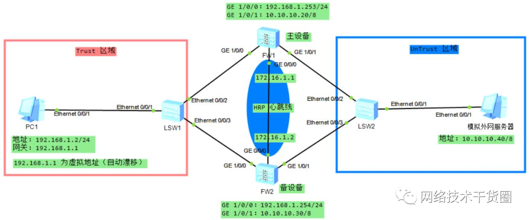
放行所有数据包(两台墙):
为了演示实验,需要手动放行数据包
# ------------------------------------------------------------
# 将默认防火墙规则,设置为允许所有
[FW1] security-policy
[FW1-policy-security] rule name anyall                   // 指定规则名称
[FW1-policy-security-rule-anyall] source-zone any        // 源地址允许所有
[FW1-policy-security-rule-anyall] destination-zone any   // 目标地址允许所有
[FW1-policy-security-rule-anyall] action permit          // 放行
[FW1-policy-security-rule-anyall] quit
[FW1-policy-security] quit# ------------------------------------------------------------
# 将指定的接口加入到指定的区域内
[FW1] firewall zone trust                                // 选择trust区域
[FW1-zone-trust] add interface GigabitEthernet 1/0/0     // 添加内部的端口
[FW1-zone-trust] quit
[FW1] firewall zone untrust                              // 添加untru区域
[FW1-zone-untrust] add interface GigabitEthernet 1/0/1   // 添加外部接口
[FW1-zone-trust] quit
配置IP地址(两台) 给防火墙的两个接口配置好IP地址.
# ------------------------------------------------------------
# 配置防火墙FW1
[FW1] interface GigabitEthernet 1/0/0                       // 选择内部接口
[FW1-GigabitEthernet1/0/0] ip address 192.168.1.253 24      // 配置防火墙IP
[FW1-GigabitEthernet1/0/0] service-manage ping permit       // 开启接口ping
[FW1-GigabitEthernet1/0/0] quit[FW1] interface GigabitEthernet1/0/1
[FW1-GigabitEthernet1/0/1] ip address 10.10.10.20 8
[FW1-GigabitEthernet1/0/1] service-manage ping permit
[FW1-GigabitEthernet1/0/1] quit# ------------------------------------------------------------
# 配置防火墙FW2
[FW2] interface GigabitEthernet 1/0/0                       // 选择内部接口
[FW2-GigabitEthernet1/0/0] ip address 192.168.1.254 24      // 配置防火墙IP
[FW2-GigabitEthernet1/0/0] service-manage ping permit       // 开启接口ping
[FW2-GigabitEthernet1/0/0] quit
[FW2-GigabitEthernet1/0/0] quit[FW2] interface GigabitEthernet1/0/1
[FW2-GigabitEthernet1/0/1] ip address 10.10.10.30 8
[FW2-GigabitEthernet1/0/1] service-manage ping permit
[FW2-GigabitEthernet1/0/1] quit
开启源NAT地址:
将内网数据映射到外网.
# ------------------------------------------------------------
# 配置防火墙FW1
[FW1] nat-policy                                                       // 配置NAT地址转换
[FW1-policy-nat] rule name tru_untr                                    // 指定策略名称
[FW1-policy-nat-rule-tru_untr] egress-interface GigabitEthernet 1/0/1  // 外网接口IP
[FW1-policy-nat-rule-tru_untr] action source-nat easy-ip               // 源地址转换
[FW1-policy-nat-rule-tru_untr] display this# ------------------------------------------------------------
# 配置防火墙FW2
[FW2] nat-policy                                                       // 配置NAT地址转换
[FW2-policy-nat] rule name tru_untr                                    // 指定策略名称
[FW2-policy-nat-rule-tru_untr] egress-interface GigabitEthernet 1/0/1  // 外网接口IP
[FW2-policy-nat-rule-tru_untr] action source-nat easy-ip               // 源地址转换
[FW2-policy-nat-rule-tru_untr] display this
开启VRRP支持(两台)
# ------------------------------------------------------------
# 配置防火墙FW1
[FW1] interface GigabitEthernet 1/0/0                                 // 选择内部接口
[FW1-GigabitEthernet1/0/0] vrrp vrid 1 virtual-ip 192.168.1.1 active  // 配置虚拟接口为主
[FW1-GigabitEthernet1/0/0] quit[FW1] interface GigabitEthernet 1/0/1                                 // 选择外部接口
[FW1-GigabitEthernet1/0/1] vrrp vrid 2 virtual-ip 10.10.10.10 active
[FW1-GigabitEthernet1/0/1] quit# ------------------------------------------------------------
# 配置防火墙FW12
[FW2] interface GigabitEthernet 1/0/0                                 // 选择内部接口
[FW2-GigabitEthernet1/0/0] vrrp vrid 1 virtual-ip 192.168.1.1 standby // 配置虚拟接口为备
[FW2-GigabitEthernet1/0/0] quit[FW2] interface GigabitEthernet 1/0/1
[FW2-GigabitEthernet1/0/1] vrrp vrid 2 virtual-ip 10.10.10.10 standby
[FW2-GigabitEthernet1/0/1] quit
HRP配置(两台):
# ------------------------------------------------------------
# 配置防火墙FW1
[FW1] hrp enable
HRP_S[FW1] hrp interface GigabitEthernet 0/0/0 remote 172.16.1.2   // 指定接口和对端IP
HRP_M[FW1] interface GigabitEthernet 0/0/0                         // 选择虚拟接口
HRP_M[FW1-GigabitEthernet0/0/0] ip address 172.16.1.1 24           // 配置本端IP地址# ------------------------------------------------------------
# 配置防火墙FW2
[FW2] hrp enable
HRP_S[FW2] hrp standby-device
HRP_S[FW2] hrp interface GigabitEthernet 0/0/0 remote 172.16.1.1
HRP_S[FW2] interface GigabitEthernet 0/0/0
HRP_S[FW2-GigabitEthernet0/0/0] ip address 172.16.1.2 24
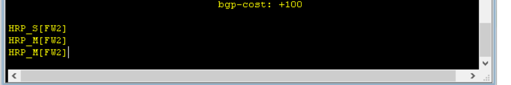
检查配置:
注意1:默认处于 standby 状态的设备不允许配置安全策略,只允许在主设 备配置安全策略,且安全策略会自动同步到备设备上面。
开启命令:hrp standby config enable
HRP_M[FW1] display hrp stateRole: active, peer: standbyRunning priority: 45000, peer: 45000Core state: normal, peer: normalBackup channel usage: 0.00%Stable time: 0 days, 0 hours, 0 minutesLast state change information: 2019-05-06 1:37:41 HRP core state changed, old_s
tate = abnormal(active), new_state = normal, local_priority = 45000, peer_priori
ty = 45000.HRP_S[FW2] display hrp stateRole: standby, peer: activeRunning priority: 45000, peer: 45000Core state: normal, peer: normalBackup channel usage: 0.00%Stable time: 0 days, 0 hours, 1 minutesLast state change information: 2019-05-06 1:37:42 HRP link changes to up.
配置负载均衡
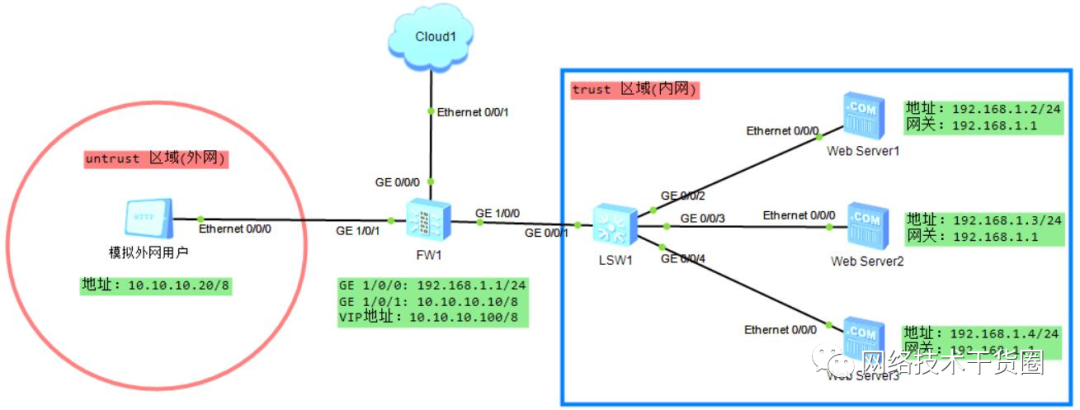
配置防火墙接口:
[FW1]interface GigabitEthernet 1/0/0
[FW1-GigabitEthernet1/0/0]ip address 192.168.1.1 24
[FW1-GigabitEthernet1/0/0]service-manage ping permit
[FW1-GigabitEthernet1/0/0]service-manage http permit
[FW1-GigabitEthernet1/0/0]quit[FW1]interface GigabitEthernet 1/0/1
[FW1-GigabitEthernet1/0/1]ip address 10.10.10.10 8
[FW1-GigabitEthernet1/0/1]service-manage ping permit
[FW1-GigabitEthernet1/0/1]service-manage http permit
[FW1-GigabitEthernet1/0/1]quit
加入相应的区域内:
[FW1]firewall zone trust
[FW1-zone-trust]add interface  GigabitEthernet 1/0/0
[FW1-zone-trust]quit[FW1]firewall zone untrust
[FW1-zone-untrust]add interface GigabitEthernet 1/0/1
[FW1-zone-untrust]quit
放行数据包:
[FW1]security-policy
[FW1-policy-security]rule name any_trust
[FW1-policy-security-rule-any_trust]source-zone any
[FW1-policy-security-rule-any_trust]destination-zone trust[FW1-policy-security-rule-any_trust]service http
[FW1-policy-security-rule-any_trust]service icmp
[FW1-policy-security-rule-any_trust]action permit
配置负载均衡:
[FW1] slb enable                                  // 启用SLB服务
[FW1] slb                                         // 进入SLB配置视图
[FW1-slb] group 1 WebServer                       // 创建服务器组webServer
[FW1-slb-group-1] metric weight-least-connection  // 使用加权轮询算法# -------------------------------------------------------
// 以下为真实服务设置   IP地址  端口 权重值 别名//[FW1-slb-group-1] rserver 1 rip 192.168.1.2 port 80 weight 1 description server1
[FW1-slb-group-1] rserver 2 rip 192.168.1.3 port 80 weight 1 description server2
[FW1-slb-group-1] rserver 3 rip 192.168.1.3 port 80 weight 1 description server3
[FW1-slb-group-1]
[FW1-slb-group-1] health-check type icmp tx-interval 5 times 3 // 配置服务健康检查参数
[FW1-slb-group-1] persistence type source-ip aging-time 180    // 配置会话保持时间
[FW1-slb-group-1] quit                                         // 返回SLB视图
[FW1-slb]
[FW1-slb] vserver 1 WebServer            // 创建虚拟服务器WebServer
[FW1-slb-vserver-1] protocol tcp         // 配置虚拟服务器的协议类型
[FW1-slb-vserver-1] vip 1 10.10.10.100   // 设置虚拟服务器IP地址
[FW1-slb-vserver-1] vport 80             // 设置虚拟服务器端
[FW1-slb-vserver-1] group WebServer      // 关联真实服务器组
[FW1-slb-vserver-1] quit                 // 返回SLB视图