参考资料:
https://blog.csdn.net/zhaoxinfan/article/details/54958641
https://blog.csdn.net/asmartkiller/article/details/84072643
https://blog.csdn.net/qq_40155300/article/details/89001808
SDK版本:2017.4
写在前面:
该文档不足以使你清楚FSBL启动的寄存器级的操作细节,但可以让你看明白整个ZYNQ7000 FSBL代码执行的主要流程。
1. ZYNQ7000加载启动流程
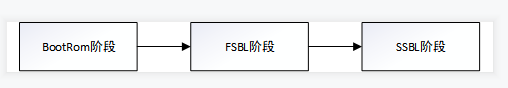
(1)BootRom阶段为ARM上电后最早加载的代码,根据MIO引脚配置确认加载方式,初始化相应的启动介质,加载FSBL到OCM中,把控制权交给FSBL
(2)FSBL阶段完成PS的初始化,加载PL bit流文件,加载SSBL引导程序或者ARM的裸机程序
(3)SSBL阶段分两种情况:①裸机程序直接在DDR中执行②uboot引导加载kernel的过程

2. FSBL代码分析
(1)在文件FSBL_bsp/standalone_v6_5/src/asm_ventors.S中,声明了一个代码段,位于地址0处。开机后PS自动执行地址0处的指令,其中第一行代码为一个跳转:B _boot
.org 0
.text.globl _vector_table.section .vectors
_vector_table:B	_bootB	UndefinedB	SVCHandlerB	PrefetchAbortHandlerB	DataAbortHandlerNOP	/* Placeholder for address exception vector*/B	IRQHandlerB	FIQHandler
(2)在同目录下找到文件boot.S中可以看到_boot标号下的代码,_boot会对系统做一系列的初始化,包括DDR,中断,MMU,cache等,执行完成后PS将具有执行C代码的能力。
可以看到在_boot代码最后又执行了一次跳转:b _start
b _start /* jump to C startup code */and r0, r0, r0 /* no op */
(3)在同目录下找到文件xil-crt0.S中可以看到_start标号下的代码,可以看到_start首先执行跳转:bl __cpu_init去执行CPU初始化操作
_start:bl __cpu_init /* Initialize the CPU first (BSP provides this) */mov r0, #0/* clear sbss */ldr r1,.Lsbss_start /* calculate beginning of the SBSS */ldr r2,.Lsbss_end /* calculate end of the SBSS */(4)在_start标号代码的末尾可以看到bsp完成了所有的初始化工作,将跳转到main函数开始执行。
/* make sure argc and argv are valid */mov r0, #0mov r1, #0/* Let her rip */bl main(5)回到FSBL工程,在目录FSBL/src/main.c中找到main函数,可以看到第一步就是调用了ps7_init()函数。
ps7_init()函数位于ps7_init.c文件中,这个C文件是由XPS根据用户的配置自动生成的。
查看ps7_init()函数,根据代码可以很明显可以看出该函数其实就是根据PS版本执行了MIO,PLL,CLK,DDR和其他外设的初始化。
int main(void)
{u32 BootModeRegister = 0;u32 HandoffAddress = 0;u32 Status = XST_SUCCESS;/** PCW initialization for MIO,PLL,CLK and DDR*/Status = ps7_init();if (Status != FSBL_PS7_INIT_SUCCESS) {fsbl_printf(DEBUG_GENERAL,"PS7_INIT_FAIL : %s\r\n",getPS7MessageInfo(Status));OutputStatus(PS7_INIT_FAIL);/** Calling FsblHookFallback instead of Fallback* since, devcfg driver is not yet initialized*/FsblHookFallback();}
int
ps7_init()
{// Get the PS_VERSION on run timeunsigned long si_ver = ps7GetSiliconVersion ();int ret;//int pcw_ver = 0;if (si_ver == PCW_SILICON_VERSION_1) {ps7_mio_init_data = ps7_mio_init_data_1_0;ps7_pll_init_data = ps7_pll_init_data_1_0;ps7_clock_init_data = ps7_clock_init_data_1_0;ps7_ddr_init_data = ps7_ddr_init_data_1_0;ps7_peripherals_init_data = ps7_peripherals_init_data_1_0;//pcw_ver = 1;} else if (si_ver == PCW_SILICON_VERSION_2) {ps7_mio_init_data = ps7_mio_init_data_2_0;ps7_pll_init_data = ps7_pll_init_data_2_0;ps7_clock_init_data = ps7_clock_init_data_2_0;ps7_ddr_init_data = ps7_ddr_init_data_2_0;ps7_peripherals_init_data = ps7_peripherals_init_data_2_0;//pcw_ver = 2;} else {ps7_mio_init_data = ps7_mio_init_data_3_0;ps7_pll_init_data = ps7_pll_init_data_3_0;ps7_clock_init_data = ps7_clock_init_data_3_0;ps7_ddr_init_data = ps7_ddr_init_data_3_0;ps7_peripherals_init_data = ps7_peripherals_init_data_3_0;//pcw_ver = 3;}// MIO initret = ps7_config (ps7_mio_init_data); if (ret != PS7_INIT_SUCCESS) return ret;// PLL initret = ps7_config (ps7_pll_init_data); if (ret != PS7_INIT_SUCCESS) return ret;// Clock initret = ps7_config (ps7_clock_init_data);if (ret != PS7_INIT_SUCCESS) return ret;// DDR initret = ps7_config (ps7_ddr_init_data);if (ret != PS7_INIT_SUCCESS) return ret;// Peripherals initret = ps7_config (ps7_peripherals_init_data);if (ret != PS7_INIT_SUCCESS) return ret;//xil_printf ("\n PCW Silicon Version : %d.0", pcw_ver);return PS7_INIT_SUCCESS;
}(6)System Software Reset,使能系统软件复位功能
/** Unlock SLCR for SLCR register write*/SlcrUnlock();(7)关闭cache功能
/** Flush the Caches*/Xil_DCacheFlush();/** Disable Data Cache*/Xil_DCacheDisable();(8)注册异常中断
/** Register the Exception handlers*/RegisterHandlers();这里相当于异常处理函数全部指向0地址。
Xil_ExceptionRegisterHandler(XIL_EXCEPTION_ID_UNDEFINED_INT,(Xil_ExceptionHandler)Undef_Handler,(void *) 0); XExc_VectorTable[Exception_id].Handler = Handler;XExc_VectorTable[Exception_id].Data = Data;
(9)DDR读写测试,在DDR不同地址段进行读写比对
/** DDR Read/write test */Status = DDRInitCheck();if (Status == XST_FAILURE) {fsbl_printf(DEBUG_GENERAL,"DDR_INIT_FAIL \r\n");/* Error Handling here */OutputStatus(DDR_INIT_FAIL);/** Calling FsblHookFallback instead of Fallback* since, devcfg driver is not yet initialized*/FsblHookFallback();}(10)Processor Configuration Access Port即处理器配置接口,连接软件和硬件的桥梁。
/** PCAP initialization*/Status = InitPcap();if (Status == XST_FAILURE) {fsbl_printf(DEBUG_GENERAL,"PCAP_INIT_FAIL \n\r");OutputStatus(PCAP_INIT_FAIL);/** Calling FsblHookFallback instead of Fallback* since, devcfg driver is not yet initialized*/FsblHookFallback();}fsbl_printf(DEBUG_INFO,"Devcfg driver initialized \r\n");
(11)获取PS版本号
/** Get the Silicon Version*/GetSiliconVersion();(12)获取PCAP接口控制器配置信息,检查是否允许系统复位
	/** Get PCAP controller settings*/PcapCtrlRegVal = XDcfg_GetControlRegister(DcfgInstPtr);/** Check for AES source key*/if (PcapCtrlRegVal & XDCFG_CTRL_PCFG_AES_FUSE_MASK) {/** For E-Fuse AES encryption Watch dog Timer disabled and* User not allowed to do system reset*/
#ifdef	XPAR_XWDTPS_0_BASEADDRfsbl_printf(DEBUG_INFO,"Watchdog Timer Disabled\r\n");XWdtPs_Stop(&Watchdog);
#endiffsbl_printf(DEBUG_INFO,"User not allowed to do ""any system resets\r\n");}
(13)配置FSBL正在执行状态
/** Store FSBL run state in Reboot Status Register*/MarkFSBLIn();(14)读取启动模式寄存器,启动模式是通过MIO引脚来配置的,要配置相应的启动模式可以参考下图中MIO各个引脚在不同模式的配置情况
/** Read bootmode register*/BootModeRegister = Xil_In32(BOOT_MODE_REG);BootModeRegister &= BOOT_MODES_MASK;

(15)根据启动模式初始化对应的存储设备
QSPI启动
①初始化qspi Flash
②MoveImage = QspiAccess;函数指针赋值,实现从Norflash中拷贝image到内存中
if (BootModeRegister == QSPI_MODE) {fsbl_printf(DEBUG_GENERAL,"Boot mode is QSPI\n\r");InitQspi();MoveImage = QspiAccess;fsbl_printf(DEBUG_INFO,"QSPI Init Done \r\n");Norlflash启动
/** NOR BOOT MODE*/if (BootModeRegister == NOR_FLASH_MODE) {fsbl_printf(DEBUG_GENERAL,"Boot mode is NOR\n\r");/** Boot ROM always initialize the nor at lower speed* This is the chance to put it to an optimum speed for your nor* device*/InitNor();fsbl_printf(DEBUG_INFO,"NOR Init Done \r\n");MoveImage = NorAccess;JTAG启动
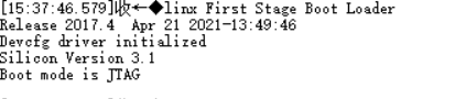
	/** JTAG  BOOT MODE*/if (BootModeRegister == JTAG_MODE) {fsbl_printf(DEBUG_GENERAL,"Boot mode is JTAG\r\n");/** Stop the Watchdog before JTAG handoff*/
#ifdef	XPAR_XWDTPS_0_BASEADDRXWdtPs_Stop(&Watchdog);
#endif/** Clear our mark in reboot status register*/ClearFSBLIn();/** SLCR lock*/SlcrLock();FsblHandoffJtagExit();
(16)FlashReadBaseAddress是在上述流程中根据不同的启动设备进行初始化的。
通常情况下我们使用Norflash启动,InitQspi()函数中会对FlashReadBaseAddress赋值,就是qspi falsh的起始地址为0xFC000000,在zynq7000的数据手册UG585中可以看到。
/** Check for valid flash address*/if ((FlashReadBaseAddress != XPS_QSPI_LINEAR_BASEADDR) &&(FlashReadBaseAddress != XPS_NAND_BASEADDR) &&(FlashReadBaseAddress != XPS_NOR_BASEADDR) &&(FlashReadBaseAddress != XPS_SDIO0_BASEADDR)) {fsbl_printf(DEBUG_GENERAL,"INVALID_FLASH_ADDRESS \r\n");OutputStatus(INVALID_FLASH_ADDRESS);FsblFallback();}/** NOR and QSPI (parallel) are linear boot devices*/if ((FlashReadBaseAddress == XPS_NOR_BASEADDR)) {fsbl_printf(DEBUG_INFO, "Linear Boot Device\r\n");LinearBootDeviceFlag = 1;}(17)接下来就是最关键的地方了,这个函数做两件事情①分析烧录到qspi中的数据的头的部分②根据分析结果拷贝数据到DDR中
/** Load boot image*/HandoffAddress = LoadBootImage();fsbl_printf(DEBUG_INFO,"Handoff Address: 0x%08lx\r\n",HandoffAddress);(18)我们进入到函数LoadBootImage()中进一步分析代码
这段代码的作用是从multiboot寄存器中读取要执行的image的地址,其实如果就一个image的话可以不用管这个,这个算出来的imagestartaddress一定是0
/** read the multiboot register*/MultiBootReg = XDcfg_ReadReg(DcfgInstPtr->Config.BaseAddr,XDCFG_MULTIBOOT_ADDR_OFFSET);fsbl_printf(DEBUG_INFO,"Multiboot Register: 0x%08lx\r\n",MultiBootReg);/** Compute the image start address*/ImageStartAddress = (MultiBootReg & PCAP_MBOOT_REG_REBOOT_OFFSET_MASK)* GOLDEN_IMAGE_OFFSET;(19)解析Image即BOOT.bin的头信息
①从bootloader中解析出BOOT.bin的大小(这个信息后续未看到有使用)
②把BOOT.bin中header解析出partition header并保存到全局变量PartHeader PartitionHeader[MAX_PARTITION_NUMBER]中,实际有效的只有3个partitions,即FSBL.elf,FPGA.bit,application.elf
③根据解析出的partition header数据解析出partition的数量
/** Get partitions header information*/Status = GetPartitionHeaderInfo(ImageStartAddress);if (Status != XST_SUCCESS) {fsbl_printf(DEBUG_GENERAL, "Partition Header Load Failed\r\n");OutputStatus(GET_HEADER_INFO_FAIL);FsblFallback();}PartHeader为BOOT.bin中解析出的各个partition的Header信息结构体
typedef struct StructPartHeader {u32 ImageWordLen;	/* 0x0 */u32 DataWordLen;	/* 0x4 */u32 PartitionWordLen;	/* 0x8 */u32 LoadAddr;		/* 0xC */u32 ExecAddr;		/* 0x10 */u32 PartitionStart;	/* 0x14 */u32 PartitionAttr;	/* 0x18 */     // 用来判断文件属性,例如FPGA.bit文件或者application.elf文件u32 SectionCount;	/* 0x1C */u32 CheckSumOffset;	/* 0x20 */u32 Pads1[1];u32 ACOffset;	/* 0x28 */u32 Pads2[4];u32 CheckSum;		/* 0x3C */
}PartHeader;
这里需要了解一下BOOT.bin的结构。
在boot.bin中从地址0-0x8BF可以分成17个部分,每个部分都有一定的含义
1. 0x000 中断向量表
2. 0x020 固定值 0xaa995566
3. 0x024 固定值 0x584c4e58 ASCII: XLNX
4. 0x028 如果是0xa5c3c5a3或者0x3a5c3c5a为加密的
5. 0x02C bootrom头版本号,不用管
6. 0x030 从bootrom开始到app地址的总数(bytes)
7. 0x034 从loadimage拷到OCM的长度 【上电后BootRom会主动把FSBL拷贝到OCM中执行】
8. 0x038 目的地址到哪儿拷贝FSBL
9. 0x03C 开始执行的地址
10. 0x040 同7 【此处代码逻辑中其实是把该字段的值赋给FSBL的size】
11. 0x044 0x01为固定值
12. 0x048 校验和(从0x020-0x047)按32-bit word 相加取反
13. 0x04C bootgen相关
14. 0x098 image头的表指针
15. 0x09C partition头的表指针
16. 0x0A0 寄存器初始化的参数
17. 0x8A0 fsbl user defined
18. 0x8C0 fsbl开始的地方 (20)拿到partition header后应该分别加载各个partition,但由于第0个partition其实就是FSBL,而我们当前其实已经在FSBL执行中了,所以不用加载直接跳过从partitionNum = 1开始加载
/** First partition header was ignored by FSBL* As it contain FSBL partition information*/PartitionNum = 1;(21)接下来开始加载对各个partition是类似的,主要完成两部分工作:
①解析并检查各个partition header中内容的正确性
②从norflash中加载各个partiton到指定的目标地址中。(这里对FPGA.bit和application.elf有所差别)
根据partition header中属性判断当前为bit文件或者application文件
if (PartitionAttr & ATTRIBUTE_PL_IMAGE_MASK) {fsbl_printf(DEBUG_INFO, "Bitstream\r\n");PLPartitionFlag = 1;PSPartitionFlag = 0;BitstreamFlag = 1;}if (PartitionAttr & ATTRIBUTE_PS_IMAGE_MASK) {fsbl_printf(DEBUG_INFO, "Application\r\n");PSPartitionFlag = 1;PLPartitionFlag = 0;ApplicationFlag = 1;}
该函数搬移partition数据到DDR中
/** Move partitions from boot device*/Status = PartitionMove(ImageStartAddress, HeaderPtr);if (Status != XST_SUCCESS) {fsbl_printf(DEBUG_GENERAL,"PARTITION_MOVE_FAIL\r\n");OutputStatus(PARTITION_MOVE_FAIL);FsblFallback();}FPGA.bit和application.elf文件都是通过下面函数依次搬移传输到DDR中
if ((LinearBootDeviceFlag && PLPartitionFlag &&(SignedPartitionFlag || PartitionChecksumFlag)) ||(LinearBootDeviceFlag && PSPartitionFlag) ||((!LinearBootDeviceFlag) && PSPartitionFlag && SecureTransferFlag)) {/** PL signed partition copied to DDR temporary location* using non-secure PCAP for linear boot device*/if(PLPartitionFlag){SecureTransferFlag = 0;LoadAddr = DDR_TEMP_START_ADDR;}/** Data transfer using PCAP*/Status = PcapDataTransfer((u32*)SourceAddr,(u32*)LoadAddr,ImageWordLen,DataWordLen,SecureTransferFlag);if(Status != XST_SUCCESS) {fsbl_printf(DEBUG_GENERAL, "PCAP Data Transfer Failed\r\n");return XST_FAILURE;}(22)如果partition为FPGA bit文件,那么通过以下函数完成从DDR中加载启动bit文件,这个函数中涉及PCAP的操作流程,这里不再深入探究。
/** Load Signed PL partition in Fabric*/if (PLPartitionFlag) {Status = PcapLoadPartition((u32*)PartitionStartAddr,(u32*)PartitionLoadAddr,PartitionImageLength,PartitionDataLength,EncryptedPartitionFlag);if (Status != XST_SUCCESS) {fsbl_printf(DEBUG_GENERAL,"BITSTREAM_DOWNLOAD_FAIL\r\n");OutputStatus(BITSTREAM_DOWNLOAD_FAIL);FsblFallback();}}(23)至此函数LoadBootImage全部执行完成,当前已完成FPGA.bit加载,并且application也已经写入到DDR中。
在下面的函数中HandoffAddress应该为application partition header中的执行地址,也是application.elf保存在DDR中的基地址,即0x00100000
/** FSBL handoff to valid handoff address or* exit in JTAG*/FsblHandoff(HandoffAddress);在该函数中最后通过FsblHandoffExit(FsblStartAddr)函数实现了FSBL到application.elf的跳转
if(FsblStartAddr == 0) {/** SLCR lock*/SlcrLock();fsbl_printf(DEBUG_INFO,"No Execution Address JTAG handoff \r\n");FsblHandoffJtagExit();} else {fsbl_printf(DEBUG_GENERAL,"SUCCESSFUL_HANDOFF\r\n");OutputStatus(SUCCESSFUL_HANDOFF);FsblHandoffExit(FsblStartAddr);}在src/fsbl_handoff.S文件中,bx lr指令实现了跳转到application开始执行
FsblHandoffExit:mov	 lr, r0	/* move the destination address into link register */mcr	 15,0,r0,cr7,cr5,0		/* Invalidate Instruction cache */mcr	 15,0,r0,cr7,cr5,6		/* Invalidate branch predictor array */dsbisb					/* make sure it completes */ldr	r4, =0mcr	 15,0,r4,cr1,cr0,0		/* disable the ICache and MMU */isb					/* make sure it completes */bx		lr	/* force the switch, destination should have been in r0 */.Ldone: b		.Ldone					/* Paranoia: we should never get here */
.end
(24)以上FSBL运行加载FPGA.bit和引导application.elf执行过程代码分析全部完成。