文章目录
- 1. Idealized Sensor
- 1.1 GPS接收器
- 1.2 AIR Sensor 执行器信息传感器
- 1.3 Beacon/OBU
- 2. Detailed Sensor
- 2.1 Camera Sensor
- 2.2 Fish eye Camera
- 2.3 Lidar
- 2.4 Radar Sensor
- 2.4 Ultrasonic Sensor
- 3. Ground Truth Sensor
- 3.1 Lane Marker Sensor
- 3.2 Analytical Lane Marker Sensor
- 3.3 Depth Camera
- 3.4 Bounding Rectangle Sensor
- 3.5 Object Camera Sensor
- 3.6 Image Segmentation Sensor
- 3.7 Point Cloud Sensor
- 4 Tripod
- 5 Physics Based
- 5.1 Physics Based Camera Sensor
- 5.2 V2X Transceiver
该笔记参考链接:
- https://blog.csdn.net/zhanshen112/article/details/88565400
Prescan中目前提供的传感器一共有三种类型:
- Idealized Sensor 理想传感器:包括了理论研究需要的传感器,适用于自动驾驶算法开发前期逻辑的验证。
- Detailed Sensor详细传感器:真实存在的传感器,对应的是有相应的传感器模型,考虑了在实际使用过程中的传感器信息的损失等(例如:雷达就考虑了路径发散衰减、大气衰减和目标反射衰减,相机则考虑相机畸变等),适用于自动驾驶算法的鲁棒性验证
- Ground-Truth Sensor真值传感器:提供的是真值(主要是视觉传感器),适用于算法的早期开发阶段
1. Idealized Sensor
理想传感器主要包括:
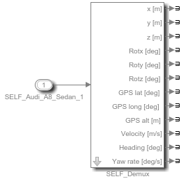
- SELF snesor/GPS receiver 自车/GPS接收器
- AIR sensor( radar/lidar/ultrasonic ) 执行器信息接收器 (挖坑)
- Antenna&DSRC transmitter/receiver 天线和DSRC的发送器/接收器(挖坑)
- Beacon/OBU 信标(信号塔)/车载单元
1.1 GPS接收器
作用:输出本车精确的GPS位置信息
PreScan中是否可以模拟GPS信号不好的这种状态?
1.2 AIR Sensor 执行器信息传感器
作用:输出目标物的检测信息
对于每个检测到的物体,都有如下参数:
Range[m] 从传感器坐标系到检测到目标物体的距离
Azimuth[deg] 方位角
Elevation[deg] 高程角
ID[n] 检测到目标的ID
Velocity[m/s] 目标物纵向速度
Heading[deg] 目标物的航向角(N-0 deg, E – 90 deg)

3种不同的可能检测方法:
Bounding Box;检测边界
Center of Bounding Box; 检测中心
Cebter of Gravity;检测质心
注意:AIR传感的局限:该传感不考虑重叠、遮挡和目标的实际形状,检测点可能落在检测范围之外。具体应用时应该根据具体情况判断。

1.3 Beacon/OBU
作用:当车载装置在beacon检测范围之内,可实现V2I通信;双向通信(Beacon依附于infrastructure上,OBU依附于车辆上)
根据传感原理,分为以下两种:
- RF射频:OBU应位于Beacon的光束中
- IR红外:OBU应位于Beacon的光束中,需要考虑遮挡
| RF | IR |
|---|---|
| fast | slower |
| no obstructed view (no occluded objects) | obstructed view (occluded objects) |
RF OBU体现为一个点,IR OBU体现为一个矩形box(尺寸可以编辑,默认0.1m)
输出参数:
- Position & orientation 位置&方位角
- Field of view 视野角度
- Range 距离(Only Beacon,默认RF 50m IR 20m)
- Cone angle (Only Beacon,默认45°)
- Maximum number of detectable OBUs (Only Beacon,默认 5)
- Maximum number of detectable beacons (Only OBU,默认 2)
2. Detailed Sensor
Detailed Sensor主要包括:
- Camera Sensor
- Fisheye Camera Sensor
- TIS:Technology Independent Sensor
- Lidar Sensor
- Radar Sensor
- Ultrasonic Sensor
2.1 Camera Sensor
作用:发送图像信息(pixels)到Simulink,便于用户自定义相应的算法(例如:车道线识别、目标分类检测、融合算法等)
可配置项:
- Position & Orientation 位置和方位
- Mono Vision /Stereo Vision 单目/双目
- Field of View 视野范围
- Resolution 分辨率
- Frame-rate 帧频率
- Color/monochrome 彩色/黑白
- Misalignment (position / orientation)
- Drift (偏移)
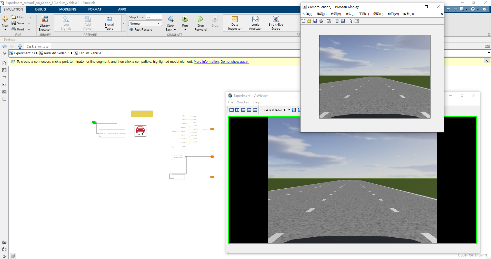
Simulink中摄像头输出:

2.2 Fish eye Camera
作用:发送图像信息(pixels)到Simulink,便于用户自定义相应的算法(例如:泊车辅助时障碍物识别等)
可配置项:

2.3 Lidar
激光雷达可用于多种目标,包括非金属物体、岩石、雨水等。
PreScan基于两种工作原理给出了对应的Lidar模型:
- pulse time-of-flight ranging
- beam modulation telemetry
这两种模型中,laser scanner都包含了发射器和接收器。

为了计算距离,被测信号的功率必须足够大。
可配置项: - 波长
- 发散角(对激光雷达而言,一般是0.01-0.08度)
- 最大目标输出数量(最大为5),针对最大目标输出数量,下面的图给出了更为具体的解释(下图max object to detect设置为3)

输出到Simulink中的数据

| Signal name | Description |
|---|---|
| ActiveBeamID[-] | ID of the beam in the current simulation time step. Value is 0 when there’s no detection. |
| Range[m] | Range at which the target object has been detected. |
| DopplerVelocity [m/s] | Velocity of target point, relative to the sensor, along the beam. |
| DopplerVelocityX/Y/Z [ms-1] | Velocity of target point, relative to the sensor, along the beam, decomposed into X,Y,Z of the sensor’s coordinate system. |
| Theta[deg] | Azimuth angle in the sensor coordinate system at which the target is detected. |
| Phi[deg] | Elevation angle in the sensor coordinate system at which the target is detected. |
| TargetID[-] | Numerical ID of the detected target. |
| TargetTypeID[-] | The Type ID of the detected object. |
| EnergyLoss[dB] | Ratio received power / transmitted power. |
| Alpha[deg] | Azimuthal incidence angle of Lidar on the target object. |
| Beta[deg] | Elevation incidence angle of Lidar on the target object. |
2.3 附 - Lidar Equation
<这部分先挖坑>
对于采用脉冲time of flight这种测量方法,假设 t r t_r tr为发射端发生信号到接收端收到信号的时间, c c c为光速,在PreScan中为常数,则Range R R R与 t r t_r tr之间的关系可以表达如下:
2 R = t r c 2R = t_r c 2R=trc
对于采用光束调制测量方法,激光由相对低频正弦波调制,因此采用的是相位进行间接测量。假设 f m o d f_{mod} fmod是调制频率, ϕ r \phi_r ϕr为发射波和接收波之间的相位差,则 t r t_r tr可以表示为:
2.4 Radar Sensor
Radar Sensor是一个更加详细的TIS传感器版本,与TIS传感器有所区别的是:
- 增加项:
- 支持对Antenna Gain Maps的使用
- 将大气衰减建模为频率和降雨的函数
- 可由外部提供扫描模式(即Simulink提供)
- 改进的Radar模型
- 删减项:
- 运用在Lidar上的pencil beam功能被移除了
- 分层阵列扫描功能被移除了(可以用多个Radar Sensor实现)

输出到Simulink中的数据
| Signal name | Description |
|---|---|
| ActiveBeamID[-] | ID of the beam in the current simulation time step. Value is 0 when there’s no detection. |
| Range[m] | Range at which the target object has been detected. |
| DopplerVelocity [ms-1] | Velocity of target point, relative to the sensor, along the line-of-sight between sensor and target point. |
| DopplerVelocityX/Y/Z[ms-1] | Velocity of target point, relative to the sensor, along the line-of-sight between sensor and target point, decomposed into X,Y,Z of the sensor’s coordinate system. |
| Theta[deg] | Azimuth angle in the sensor coordinate system at which the target is detected. |
| Phi[deg] | Elevation angle in the sensor coordinate system at which the target is detected. |
| TargetID[-] | Numerical ID of the detected target. |
| TargetTypeID[-] | The Type ID of the detected object. |
| EnergyLoss[dB] | Ratio received power / transmitted power. |
| Alpha[deg] | Azimuthal incidence angle of the Radar beam on the target object. |
| Beta[deg] | Elevation incidence angle of the Radar beam on the target object. |


车载雷达的分类及基本属性
| 类型 | 工作形式 | 频率 | 覆盖距离 | 水平视角 | 应用场景 |
|---|---|---|---|---|---|
| SRR短距雷达 | 脉冲 | 24GHz | 30m | ±65°~±80° | BSD、PA、LCA、FCW、RCW |
| MRR中距离雷达 | 连续波/脉冲 | 24GHz / 76-77GHz | 70m | ±40°~±50° | LCA |
| LRR长距离雷达 | 连续波/脉冲 | 76-77GHz | 200m | ±4°~±8° | ACC |
2.4 Ultrasonic Sensor
反射强度取决于透射波的强度、辐射模式、到物体的距离、介质的透射率和目标物体的特性。
输出到Simulink中的数据

| signal name | description |
|---|---|
| ObjectDetection[-] | Indicates if an object is detected. (1 if an object is detected, 0 otherwise) |
| Range[m] | Range at which the target object has been detected. |
| DopplerVelocity [ms-1] | Velocity of target point, relative to the sensor, along the line-of-sight between sensor and target point. |
| DopplerVelocityX/Y/Z[ms-1] | Velocity of target point, relative to the sensor, along the line-of-sight between sensor and target point, decomposed into X,Y,Z of the sensor’s coordinate system. |
| Theta[deg] | Azimuth angle in the sensor coordinate system at which the target is detected. |
| Phi[deg] | Elevation angle in the sensor coordinate system at which the target is detected. |
| TargetID[-] | Numerical ID of the detected target. |
| TargetTypeID[-] | The Type ID of the detected object. |
| EnergyLoss[dB] | Ratio received power / transmitted power, same as ΔSPL. |
| Alpha[deg] | Azimuthal incidence angle of sound wave on the target object. |
| Beta[deg] | Elevation incidence angle of sound wave on the target object. |
3. Ground Truth Sensor
3.1 Lane Marker Sensor
lane marker传感器提供道路上存在的车道线信息。
输出到Simulink的数据

输出结果以Bus形式给出,主要包括了5个信号:
- sliceCout [int] 前视距离数量
- ScanAtSensor [sub-bus:LaneMarkerSliceData]
- ScanAtDistance1(,2,3)
3.2 Analytical Lane Marker Sensor
分析车道标志传感器是车道传感器的一种新的实现方法,提供道路上车道线的信息。
车道线信息以多项式的形式给出,需要注意一下,因为是用多项式进行车道线的拟合,所以这个传感器输出的在一定程度上不算是真值,是对真值的逼近。
该传感器仅考虑传感器视野范围内的车道线,同一条车道线在视野范围内穿过了,会视为不同的车道线。


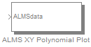
 在Simulink中可视化车道线,可以借助Prescan提供的’ALMS XY Polynomial Plot’实现,该模块利用
open('PreScanUsefulBlocks')查找。
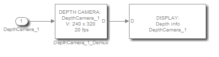
3.3 Depth Camera
Depth摄像机包含的是深度值,用来校准和验证双目相机的深度计算。
输出到Simulink的数据
深度的分辨率是非线性的,如下:
d = z 2 z n e a r 2 24 − z d = \frac{z^2}{z_{near}2^{24} - z} d=znear224−zz2
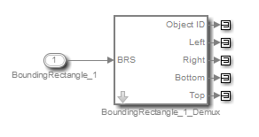
3.4 Bounding Rectangle Sensor
bounding rectangle传感器提供传感器可检测目标的包围矩形信息,并为相机的bounding rectangle算法做参考。例如行人识别算法,实现照明条件不良情况下的行人检测,输出按距离排序。
输出到Simulink的数据

在Simulink中可视化bounding box,可以借助Prescan提供的’BRS data on Camera image’实现,该模块利用open('PreScanUsefulBlocks')查找。
3.5 Object Camera Sensor
该传感器对包含摄像机单元和图像处理单元的系统进行建模。此外,它还提供了有关目标的距离和多普勒速度信息。
OCS传感器检测所有标记为sensor detectable的目标物。
输出到Simulink的数据

| Signal | Description |
|---|---|
| Object ID [-] | Numerical ID of the detected object. |
| ObjectTypeID [-] The Type ID of the detected object. | |
| Left [-] | Horizontal screen coordinate of the left side of the bounding box |
| Right [-] | Horizontal screen of the right side of the bounding box |
| Bottom [-] | Vertical screen coordinate of the bottom side of the bounding box |
| Top [-] | Vertical screen coordinate of the top side of the bounding box |
| Range [m] | Range at which the target object has been detected. The distance to the nearest point is returned. |
| RangeX [m] | X component of the Range, in sensor coordinates. |
| RangeY [m] | Y component of the Range, in sensor coordinates. |
| RangeZ [m] | Z component of the Range, in sensor coordinates. |
| DopplerVelocity [m/s] | Velocity of target point, relative to the sensor, along the line-of-sight between sensor and target point. |
| DopplerVelocityX/Y/Z[m/s] | Velocity of target point, relative to the sensor, along the line-of-sight between sensor and target point, decomposed into X,Y,Z of the sensor’s coordinate system. |
| Theta [deg] | Azimuth angle in the sensor’s coordinate system at which the target is detected. |
| Phi [deg] | Elevation angle in the sensor’s coordinate system at which the target is detected. |
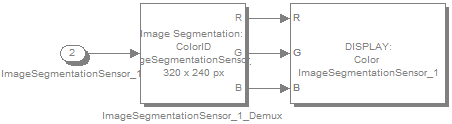
3.6 Image Segmentation Sensor
ISS传感器输出到Simulink的数据

3.7 Point Cloud Sensor
点云传感器用于构建周边环境的点云,用于算法的开发、激光雷达的尺寸验证以及HIL测试。
基本参数:
| Parameter | Description | Defaut | Min. | Max. |
|---|---|---|---|---|
| FoV in Azimuth[deg] | The horizontal field of view of the sensor in degrees. | 60 | 0.1 | 120 |
| FoV in Elevation[deg] | For each azimuth direction, the same vertical field of view in degrees. | 30 | 0.1 | 60 |
| #horizontal samples | The number of equi-angular-distant samples in the azimuth direction. | 320 | 1 | 3840 |
| #vertical samples | The number of equi-angular-distant samples in the elevation direction. | 160 | 1 | 2160 |
传感器输出到Simulink的数据
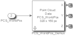
PCS mux for World Position
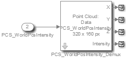
PCS mux for World Position and Intensity
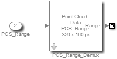
PCS mux for Range.
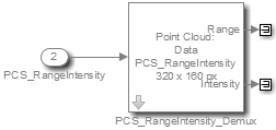
PCS mux for Range and Intensity.
Data Model API通过matlab脚本提供了对传感器参数的便捷式访问。
%% Sample code for configuring the PCS via the Data Model API
%% Part 1
% Get the model
models = prescan.experiment.readDataModels();
% Find camera sensor CameraSensor_1
sensorData = prescan.sensors.findByName(models, 'PointCloudSensor_1');% Exit the script when the sensor is not found
if isempty(sensorData)
display('Sensor with the specified name is not found.');
return;
end%% Part 2
% Create copies of point cloud sensor structures
sensor = models.(sensorData{1}.modelName).sensor{sensorData{1}.indices(1)};
pointCloudSensor = sensor.pointCloudSensor;
sensorBase = sensor.sensorBase;
% Update settings
pointCloudSensor.sensorOutputMode = 'worldPosition'; % Can also be 'range'.
pointCloudSensor.outputIntensity = false;
pointCloudSensor.nearClippingDistance = 0.1; % [m]
pointCloudSensor.farClippingDistance = 150; % [m]
pointCloudSensor.extrapolateRange = true;
pointCloudSensor.sampleAccuracy.x = 0.05; % [deg]
pointCloudSensor.sampleAccuracy.y = 0.05; % [deg]
pointCloudSensor.integerOutput = false; % Do not use sensorOutputMode =
%'worldPosition' with integerOutput = true.
% Doing so will result in undefined
behaviour.
%sensorBase.name = 'PointCloudSensor_1';
sensorBase.fovAzimuth = 60 * pi/180; % [rad]
sensorBase.fovElevation = 30 * pi/180; % [rad]
sensor.resolution.x = 320; % [#samples]
sensor.resolution.y = 160; % [#samples]
sensor.frameRate = int32(20); % [Hz]% Configure sensor's pose, defaults depend on the actor it is placed on.
% sensorBase.relativePose.position.x = 1.56; % [m]
% sensorBase.relativePose.position.y = 0; % [m]
% sensorBase.relativePose.position.z = 1.22; % [m]
% sensorBase.relativePose.orientation.roll = 0; % [rad]
% sensorBase.relativePose.orientation.pitch = 0; % [rad]
% sensorBase.relativePose.orientation.yaw = 0; % [rad]
% Copy updated structures back into the model.
sensor.pointCloudSensor = pointCloudSensor;
sensor.sensorBase = sensorBase;
models.cameramodel.sensor{1} = sensor;%% Part 3
% Run the experiment for 10 seconds
simOut = prescan.experiment.runWithDataModels(models, 'StopTime', '10.0');
4 Tripod
目的:用来进行传感器标定,Tripod对传感器是不可见的。
5 Physics Based
5.1 Physics Based Camera Sensor
5.2 V2X Transceiver
以上两个目前没有用到,先挖坑吧