版权声明:本文为博主原创文章,未经博主允许不得转载。
https://blog.csdn.net/huangweiqing80/article/details/83112671
一、Pci的地址域
PCI总线协议中定义了三个不同的地址空间:1、PCI配置空间;2、PCI memory空间;3、PCI的IO空间。如果对PCI没有形成一点感念的初学者,很难理解这几个空间的区别。
简单的说,PCI配置空间是PCI设备的内部属性,设备内部保存了256bytes的空间作为内部register定义该设备的属性。访问配置空间使用IO读写(X86架构中使用CF8h/CFCh端口);而PCI设备的memory/IO空间则是映射到CPU地址域中,需要占用的memory/IO地址空间。访问这部分地址域只要使用简单直接的memory、IO访问方式就可以实现。
每个PCI设备的配置空间数据都不一样。基本上都是以固定的形式。每个外围设备在其 PCI 配置空间中都包含一组明确定义的配置寄存器。这些寄存器不仅用于标识设备,还用于提供设备配置信息。生成配置周期的方法取决于主机架构,x86 计算机中使用的是特殊的 I/O 端口(CF8h/CFCh端口)。在其他平台上,可以将 PCI 配置空间内存映射到对应于主机地址域中 PCI 主桥 (host bridge) 的某些地址位置,比如MIPS架构中。
二、PCI寻址
我们先来看一个例子,我的电脑装有1G的RAM,1G以后的物理内存地址空间都是外部设备IO在系统内存地址空间上的映射。/proc/iomem描述了 系统中所有的设备I/O在内存地址空间上的映射。我们来看地址从1G开始的第一个设备在/proc/iomem中是如何描述的:
40000000-400003ff : 0000:00:1f.1
这是一个PCI设备,40000000-400003ff是它所映射的内存地址空间,占据了内存地址空间的1024 bytes的位置,而0000:00:1f.1则是一个PCI外设的地址,它以冒号和逗号分隔为4个部分,第一个16位表示域,第二个8位表示一个总线编 号,第三个5位表示一个设备号,最后是3位,表示功能号。
因为PCI规范允许单个系统拥有高达256个总线,所以总线编号是8位。但对于大型系统而言,这是不够的,所以,引入了域的概念,每个PCI域可以拥有最 多256个总线,每个总线上可支持32个设备,所以设备号是5位,而每个设备上最多可有8种功能,所以功能号是3位。由此,我们可以得出上述的PCI设备 的地址是0号域0号总线上的31号设备上的1号功能。那上述的这个PCI设备到底是什么呢?下面是我的电脑上的lspci命令的输出:
00:00.0 Host bridge: Intel Corporation 82845 845 (Brookdale) Chipset Host Bridge (rev 04)00:01.0 PCI bridge: Intel Corporation 82845 845 (Brookdale) Chipset AGP Bridge(rev 04)00:1d.0 USB Controller: Intel Corporation 82801CA/CAM USB (Hub #1) (rev 02)00:1d.1 USB Controller: Intel Corporation 82801CA/CAM USB (Hub #2) (rev 02)00:1e.0 PCI bridge: Intel Corporation 82801 Mobile PCI Bridge (rev 42)00:1f.0 ISA bridge: Intel Corporation 82801CAM ISA Bridge (LPC) (rev 02)00:1f.1 IDE interface: Intel Corporation 82801CAM IDE U100 (rev 02)00:1f.3 SMBus: Intel Corporation 82801CA/CAM SMBus Controller (rev 02)00:1f.5 Multimedia audio controller:Intel Corporation 82801CA/CAM AC'97 Audio Controller (rev 02)00:1f.6 Modem: Intel Corporation 82801CA/CAM AC'97 Modem Controller (rev 02)01:00.0 VGA compatible controller: nVidia Corporation NV17 [GeForce4 420 Go](rev a3)02:00.0 FireWire (IEEE 1394): VIA Technologies, Inc. IEEE 1394 Host Controller(rev 46)02:01.0 Ethernet controller: Realtek Semiconductor Co., Ltd. RTL-8139/8139C/8139C+(rev 10)02:04.0 CardBus bridge: O2 Micro, Inc. OZ6933 Cardbus Controller (rev 01)02:04.1 CardBus bridge: O2 Micro, Inc. OZ6933 Cardbus Controller (rev 01)
lspci 没有标明域,但对于一台PC而言,一般只有一个域,即0号域。通过这个输出我们可以看到它是一个IDE interface。由上述的输出可以看到,我的电脑上共有3个PCI总线(0号,1号,2号)。在单个系统上,插入多个总线是通过桥(bridge)来 完成的,桥是一种用来连接总线的特殊PCI外设。所以,PCI系统的整体布局组织为树型,我们可以通过上面的lspci输出,来画出我的电脑上的PCI系 统的树型结构:
00:00.0(主桥)--00:01.0(PCI桥)-----01:00:0(nVidia显卡)||---00:1d(USB控制器)--00:1d:0(USB1号控制器)| || |--00:1d:1(USB2号控制器) ||-00:1e:0(PCI桥)--02:00.0(IEEE1394)| || |-02:01.0(8139网卡)| || |-02:04(CardBus桥)-02:04.0(桥1)| || |--02:04.1(桥2)||-00:1f(多功能板卡)-00:1f:0(ISA桥)||--00:1f:1(IDE接口)||--00:1f:3(SMBus)||--00:1f:5(多媒体声音控制器)||--00:1f:6(调制解调器)
由上图可以得出,我的电脑上共有8个PCI设备,其中0号总线上(主桥)上连有4个,1号总线上连有1个,2号总线上连有3个。00:1f是一个连有5个功能的多功能板卡。
每一个PCI设备都有它映射的内存地址空间和它的I/O区域,这点是比较容易理解的。除此之外,PCI设备还有它的配置寄存器。有了配置寄存器,PCI的 驱动程序就不需要探测就能访问设备。配置寄存器的布局是标准化的,配置空间的4个字节含有一个独一无二的功能ID,因此,驱动程序可通过查询外设的特定 ID来识别其设备。所以,PCI接口标准在ISA之上的主要创新在于配置地址空间。
三 、linux中pci设备知识
Linux PCI设备驱动实际包括Linux PCI设备驱动和设备本身驱动两部分。PCI(Periheral Component Interconnect)有三种地址空间:PCI I/O空间、PCI内存地址空间和PCI配置空间。其中,PCI I/O空间和PCI内存地址空间由设备驱动程序使用,而PCI配置空间由Linux PCI初始化代码使用,用于配置PCI设备,比如中断号以及I/O或内存基地址。
3.1 内核工作
Linux内核主要就做了对PCI设备的枚举和配置;在Linux内核初始化时完成的。
对于PCI总线,有一个叫做PCI桥的设备用来将父总线与子总线连接。作为一种特殊的PCI设备,PCI桥主要包括以下三种:
1). Host/PCI桥: 用于连接CPU与PCI根总线,第1个根总线的编号为0。在PC中,内存控制器也通常被集成到Host/PCI桥设备芯片中,因此Host/PCI桥通常也被称为“北桥芯片组(North Bridge Chipset)”。
2). PCI/ISA桥: 用于连接旧的ISA总线。通常,PCI中类似i8359A中断控制器这样的设备也会被集成到PCI/ISA桥设备中。因此,PCI/ISA桥通常也被称为“南桥芯片组(South Bridge Chipset)”
3). PCI-to-PCI桥(以下称为PCI-PCI桥): 用于连接PCI主总线(Primary Bus)和次总线(Secondary Bus)。PCI-PCI桥所处的PCI总线称为主总线,即次总线的父总线;PCI-PCI桥所连接的PCI总线称为次总线,即主总线的子总线。
3.1.2 遍历
从Host/PCI桥开始进行探测和扫描,逐个“枚举”连接在第一条PCI总线上的所有设备并记录在案。如果其中的某个设备是PCI-PCI桥,则又进一步再探测和扫描连在这个桥上的次级PCI总线。就这样递归下去,直到穷尽系统中的所有PCI设备。其结果,是在内存中建立起一棵代表着这些PCI总线和设备的PCI树。
每个PCI设备(包括PCI桥设备)都由一个pci_dev结构体来表示,而每条PCI总线则由pci_bus结构来表示。
3.1.3 配置
PCI设备中一般都带有一些RAM和ROM 空间,通常的控制/状态寄存器和数据寄存器也往往以RAM区间的形式出现,而这些区间的地址在设备内部一般都是从0开始编址的,那么当总线上挂接了多个设备时,对这些空间的访问就会产生冲突。所以,这些地址都要先映射到系统总线上,再进一步映射到内核的虚拟地址空间。
配置就是通过对PCI配置空间的寄存器进行操作从而完成地址的映射。
1.1.4 数据结构
pci_driver数据结构定义在:include/linux/pci.h文件中。
struct pci_driver {struct list_head node;const char *name;const struct pci_device_id *id_table;	/* must be non-NULL for probe to be called */int  (*probe)  (struct pci_dev *dev, const struct pci_device_id *id);	/* New device inserted */void (*remove) (struct pci_dev *dev);	/* Device removed (NULL if not a hot-plug capable driver) */int  (*suspend) (struct pci_dev *dev, pm_message_t state);	/* Device suspended */int  (*suspend_late) (struct pci_dev *dev, pm_message_t state);int  (*resume_early) (struct pci_dev *dev);int  (*resume) (struct pci_dev *dev);	                /* Device woken up */void (*shutdown) (struct pci_dev *dev);struct pci_error_handlers *err_handler;struct device_driver	driver;struct pci_dynids dynids;
};
pci_dev也定义在include/linux/pci.h文件中。
详细描述了一个PCI设备几乎所有的硬件信息,包括厂商ID、设备ID、各种资源等.
/** The pci_dev structure is used to describe PCI devices.*/
struct pci_dev {struct list_head bus_list;	/* node in per-bus list */struct pci_bus	*bus;		/* bus this device is on */struct pci_bus	*subordinate;	/* bus this device bridges to */void		*sysdata;	/* hook for sys-specific extension */struct proc_dir_entry *procent;	/* device entry in /proc/bus/pci */struct pci_slot	*slot;		/* Physical slot this device is in */unsigned int	devfn;		/* encoded device & function index */unsigned short	vendor;unsigned short	device;unsigned short	subsystem_vendor;unsigned short	subsystem_device;unsigned int	class;		/* 3 bytes: (base,sub,prog-if) */u8		revision;	/* PCI revision, low byte of class word */u8		hdr_type;	/* PCI header type (`multi' flag masked out) */u8		pcie_cap;	/* PCI-E capability offset */u8		pcie_type:4;	/* PCI-E device/port type */u8		pcie_mpss:3;	/* PCI-E Max Payload Size Supported */u8		rom_base_reg;	/* which config register controls the ROM */u8		pin;  		/* which interrupt pin this device uses */struct pci_driver *driver;	/* which driver has allocated this device */u64		dma_mask;	/* Mask of the bits of bus address thisdevice implements.  Normally this is0xffffffff.  You only need to changethis if your device has broken DMAor supports 64-bit transfers.  */struct device_dma_parameters dma_parms;pci_power_t     current_state;  /* Current operating state. In ACPI-speak,this is D0-D3, D0 being fully functional,and D3 being off. */int		pm_cap;		/* PM capability offset in theconfiguration space */unsigned int	pme_support:5;	/* Bitmask of states from which PME#can be generated */unsigned int	pme_interrupt:1;unsigned int	pme_poll:1;	/* Poll device's PME status bit */unsigned int	d1_support:1;	/* Low power state D1 is supported */unsigned int	d2_support:1;	/* Low power state D2 is supported */unsigned int	no_d1d2:1;	/* Only allow D0 and D3 */unsigned int	mmio_always_on:1;	/* disallow turning off io/memdecoding during bar sizing */unsigned int	wakeup_prepared:1;unsigned int	d3_delay;	/* D3->D0 transition time in ms */#ifdef CONFIG_PCIEASPMstruct pcie_link_state	*link_state;	/* ASPM link state. */
#endifpci_channel_state_t error_state;	/* current connectivity state */struct	device	dev;		/* Generic device interface */int		cfg_size;	/* Size of configuration space *//** Instead of touching interrupt line and base address registers* directly, use the values stored here. They might be different!*/unsigned int	irq;struct resource resource[DEVICE_COUNT_RESOURCE]; /* I/O and memory regions + expansion ROMs *//* These fields are used by common fixups */unsigned int	transparent:1;	/* Transparent PCI bridge */unsigned int	multifunction:1;/* Part of multi-function device *//* keep track of device state */unsigned int	is_added:1;unsigned int	is_busmaster:1; /* device is busmaster */unsigned int	no_msi:1;	/* device may not use msi */unsigned int	block_cfg_access:1;	/* config space access is blocked */unsigned int	broken_parity_status:1;	/* Device generates false positive parity */unsigned int	irq_reroute_variant:2;	/* device needs IRQ rerouting variant */unsigned int 	msi_enabled:1;unsigned int	msix_enabled:1;unsigned int	ari_enabled:1;	/* ARI forwarding */unsigned int	is_managed:1;unsigned int	is_pcie:1;	/* Obsolete. Will be removed.Use pci_is_pcie() instead */unsigned int    needs_freset:1; /* Dev requires fundamental reset */unsigned int	state_saved:1;unsigned int	is_physfn:1;unsigned int	is_virtfn:1;unsigned int	reset_fn:1;unsigned int    is_hotplug_bridge:1;unsigned int    __aer_firmware_first_valid:1;unsigned int	__aer_firmware_first:1;pci_dev_flags_t dev_flags;atomic_t	enable_cnt;	/* pci_enable_device has been called */u32		saved_config_space[16]; /* config space saved at suspend time */struct hlist_head saved_cap_space;struct bin_attribute *rom_attr; /* attribute descriptor for sysfs ROM entry */int rom_attr_enabled;		/* has display of the rom attribute been enabled? */struct bin_attribute *res_attr[DEVICE_COUNT_RESOURCE]; /* sysfs file for resources */struct bin_attribute *res_attr_wc[DEVICE_COUNT_RESOURCE]; /* sysfs file for WC mapping of resources */
#ifdef CONFIG_PCI_MSIstruct list_head msi_list;struct kset *msi_kset;
#endifstruct pci_vpd *vpd;
#ifdef CONFIG_PCI_ATSunion {struct pci_sriov *sriov;	/* SR-IOV capability related */struct pci_dev *physfn;	/* the PF this VF is associated with */};struct pci_ats	*ats;	/* Address Translation Service */
#endif
};static inline struct pci_dev *pci_physfn(struct pci_dev *dev)
{
#ifdef CONFIG_PCI_IOVif (dev->is_virtfn)dev = dev->physfn;
#endifreturn dev;
}
1.1.5 pci初始化流程顺序
pci这块代码在两个地方,一个是driver/pci,另一个是arch/x86/pci中。
-
pci系统的初始化工作有内核来完成,在drivers/pci/probe.c文件中,调用postcore_initcall(pcibus_class_init);函数,在sys/class/下创建一个pci_bus目录
-
drivers/pci/pci-driver.c文件,postcore_initcall(pci_driver_init); 注册pci总线,并在/sys/bus/下创建了一个pci目录
-
arch/x86/pci/init.c文件中arch_initcall(pci_arch_init);体系架构相关,对于64 bit x86来说使用CONFIG_PCI_DIRECT的方式进行访问PCI配置空间。在内核编译时候可以指定。
-
drivers/pci/pci-acpi.c文件中,调用arch_initcall(acpi_pci_init);
-
arch/x86/pci/legacy.c文件中,调用subsys_initcall(pci_subsys_init);
-
drivers/pci/slot.c文件中,subsys_initcall(pci_slot_init); 创建/sys/bus/slots文件。
四、pci架构概貌
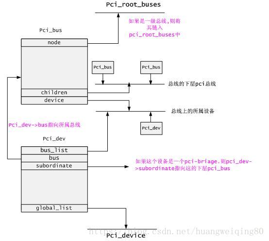
上图展现了pci驱动架构中,pci_bus.pci_dev之间的关系.
如上图所示:所有的根总线都链接在pci_root_buses链表中. Pci_bus ->device链表链接着该总线下的所有设备.而pci_bus->children链表链接着它的下层总线.
对于pci_dev来说,pci_dev->bus指向它所属的pci_bus. Pci_dev->bus_list链接在它所属bus的device链表上.此外,所有pci设备都链接在pci_device链表中.
五、PCI设备与配置空间
在i386系统结构中,对内存的访问和对输入/输出寄存器的访问通过两套不同的指令完成,所有的存储器和IO两个不同的地址空间。一般而言,内存的物理地址以及输入/输出寄存器的地址是由硬件决定的,不过对于内存的物理地址还可以通过地址映射机制来一次转换(I/O也可以映射)。可是,怎样处理外设的存储空间呢?理想的办法是系统软件自动设置,思路是:
1、外设通过某种途径告诉系统,它有几个存储区间以及I/O地址空间,每个区间是多大,以及各自在本地的地址,显然这些地址都是局部的内部的,都从0开始算起。
2、系统软件在知道了一共有多少外设,各自又有什么样的存储区间以后,就可以为这些区间分配“物理地址”,并且建立起这些区间与总线之间的连接,以后就可以通过这些地址来访问。显然,这里所谓的“物理地址”与真正的物理地址还是有些区别的,它实际上也是一种逻辑地址,所以常称为“总线地址”,因为这是CPU在总线上所看到的地址。可想而知,外设上一定有着某种地址映射机制。所谓的“为外设分配地址”,就是为其分配总线地址,并建立起映射。
PCI设备上存在许多完成上述工作的寄存器(配置空间),那么系统初始化的时候如何访问这些寄存器?对于i386结构的处理器,PCI总线的设计者在I/O地址空间保留了8个字节用于这个目的,那就是0xCF8~0xCFF,这8个字节的地址空间构成了两个32位的寄存器,第一个是“地址寄存器”0xCF8,第二个是“数据寄存器”0xCFC,要访问配置空间的寄存器时,CPU先向地址寄存器(0xCF8)写入目标地址(PCI设备配置空间寄存器地址),然后通过数据寄存器进行读写数据。不过,写入地址寄存器的目标地址是一种包括总线号、设备号、功能号以及配置寄存器地址的综合地址。每个PCI设备最多有8个功能,所以设备号和功能号组合在一起又被称作“逻辑设备”号。
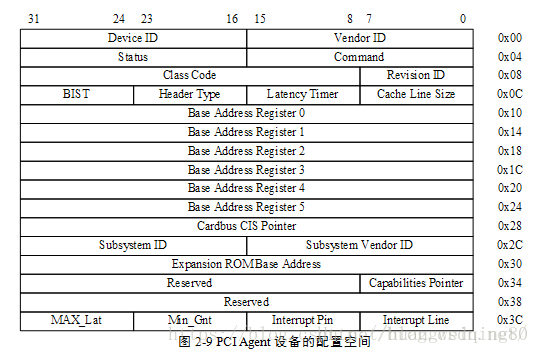
如上图所示,PCI标准规定每个设备的配置寄存器组最多可以有256字节的连续空间,其中开头的64字节的用途和格式是标准的,成为配置寄存器组的“头部”,这样的头部又有两种,“0型”头部用于一般的PCI设备,“1型”头部用于PCI桥,无论是“0型”还是“1型”,其开头的16个字节的用途和格式是共同的。
六、PCI驱动之总线
在内核中与PCI相关的结构体大概有pci_driver 、pci_bus_type 、pci_dev 、pci_bus ,我们前边所说的所有的PCI总线都是指的 pci_bus 。
6.1 pci_bus
struct pci_bus {struct list_head node;		/* node in list of buses */struct pci_bus	*parent;	/* parent bus this bridge is on */struct list_head children;	/* list of child buses */struct list_head devices;	/* list of devices on this bus */struct pci_dev	*self;		/* bridge device as seen by parent */struct list_head slots;		/* list of slots on this bus */struct resource	*resource[PCI_BUS_NUM_RESOURCES];/* address space routed to this bus */struct pci_ops	*ops;		/* configuration access functions */void		*sysdata;	/* hook for sys-specific extension */struct proc_dir_entry *procdir;	/* directory entry in /proc/bus/pci */unsigned char	number;		/* bus number */unsigned char	primary;	/* number of primary bridge */unsigned char	secondary;	/* number of secondary bridge */unsigned char	subordinate;	/* max number of subordinate buses */char		name[48];unsigned short  bridge_ctl;	/* manage NO_ISA/FBB/et al behaviors */pci_bus_flags_t bus_flags;	/* Inherited by child busses */struct device		*bridge;struct device		dev;struct bin_attribute	*legacy_io; /* legacy I/O for this bus */struct bin_attribute	*legacy_mem; /* legacy mem */unsigned int		is_added:1;
};
几个重要的成员:
children: PCI桥可以使当前总线得到扩展,当前总线上有几个PCI桥,那么当前总线就会拥有几个子总线,子总线会连接到父总线的children链表中。
device: 连接在这条总线上的设备链表。
ops: 当前总线访问总线上设备配置空间的 read、write 方法。
在内核启动的过程中,首先会创建0级总线,然后枚举探测0级总线上的设备,如果是PCI桥,那么还要进入下一级子总线,最终所有的连接的PCI设备都将被探测到,详细的探测过程,我们在后边分析。
6.2 注册pci总线
struct bus_type pci_bus_type = {.name		= "pci",.match		= pci_bus_match,.uevent		= pci_uevent,.probe		= pci_device_probe,.remove		= pci_device_remove,.shutdown	= pci_device_shutdown,.dev_attrs	= pci_dev_attrs,.bus_attrs	= pci_bus_attrs,.pm		= PCI_PM_OPS_PTR,
};static int __init pci_driver_init(void)
{return bus_register(&pci_bus_type);
}postcore_initcall(pci_driver_init);
3.3 pci_bus_type
看到 bus_type 显然这是个设备总线驱动模型里的“总线”,与前边提到的 pci_bus ,完全是两码事,那么pci_driver 和 pci_dev 就是注册到 pci_bus_type 的驱动和设备。分析总线设备驱动模型的时候,总要分析一下它的 match 函数(匹配规则)。
static int pci_bus_match(struct device *dev, struct device_driver *drv)
{struct pci_dev *pci_dev = to_pci_dev(dev);struct pci_driver *pci_drv = to_pci_driver(drv);const struct pci_device_id *found_id;found_id = pci_match_device(pci_drv, pci_dev);if (found_id)return 1;return 0;
}
static const struct pci_device_id *pci_match_device(struct pci_driver *drv,struct pci_dev *dev)
{struct pci_dynid *dynid;/* Look at the dynamic ids first, before the static ones */spin_lock(&drv->dynids.lock);list_for_each_entry(dynid, &drv->dynids.list, node) {if (pci_match_one_device(&dynid->id, dev)) {spin_unlock(&drv->dynids.lock);return &dynid->id;}}spin_unlock(&drv->dynids.lock);return pci_match_id(drv->id_table, dev);
}static inline const struct pci_device_id *
pci_match_one_device(const struct pci_device_id *id, const struct pci_dev *dev)
{if ((id->vendor == PCI_ANY_ID || id->vendor == dev->vendor) &&(id->device == PCI_ANY_ID || id->device == dev->device) &&(id->subvendor == PCI_ANY_ID || id->subvendor == dev->subsystem_vendor) &&(id->subdevice == PCI_ANY_ID || id->subdevice == dev->subsystem_device) &&!((id->class ^ dev->class) & id->class_mask))return id;return NULL;
}const struct pci_device_id *pci_match_id(const struct pci_device_id *ids,struct pci_dev *dev)
{if (ids) {while (ids->vendor || ids->subvendor || ids->class_mask) {if (pci_match_one_device(ids, dev))return ids;ids++;}}return NULL;
}通过分析代码,PCI设备与驱动的匹配方式有两种,一种是通过 pci_driver->dynids ,另一种是通过 pci_driver->idtable 。使用idtable 是总线设备驱动模型中常用的匹配方法,一般都是通过设备名来匹配,但是PCI比较特殊,它是通过设备的 vendor 、subvendor 、device 、subdevice 来匹配(这些都是在配置空间里可以读取到的)。
至于 pci_driver->dynids ,它是通过用户空间给驱动增加匹配条件的一种方法(还记得I2C可以在用户空间创建设备吗,一样的)。
error = pci_create_newid_file(drv);
static int
pci_create_newid_file(struct pci_driver *drv)
{int error = 0;if (drv->probe != NULL)error = driver_create_file(&drv->driver, &driver_attr_new_id);return error;
}
在 pci_register_driver 函数中会调用到一个 pci_create_newid_file 函数,它在 sysfs 文件系统中会创建一个 new_id 的属性文件,通过这个属性文件,我们就可以来为该驱动增加匹配条件。
内核帮助文档有说明:
New PCI IDs may be added to a device driver pci_ids table at runtime as shown below:
echo "vendor device subvendor subdevice class class_mask driver_data" > \
/sys/bus/pci/drivers/{driver}/new_id
对于这种方法不在详细分析。
分析完设备总线驱动模型,我想整个PCI驱动的框架就非常清楚了,内核启动时,通过pci_bus之间的关系枚举出所有的 PCI 设备,并为每一个 PCI 设备创建一个 pci_dev ,根据配置空间的信息填充 pci_dev 之后,注册到pci_bus_type 。而,我们写的 pci_driver 在 idtable 里指定它所支持的设备信息,同样也注册到 pci_bus_type中去,信息一致匹配成功则调用 driver->probe 函数,然后你可以注册字符设备、块设备等等。
本文参考了
https://blog.csdn.net/notbaron/article/details/79643799
https://blog.csdn.net/notbaron/article/details/80346988
https://blog.csdn.net/zyboy2000/article/details/51971453
http://blog.chinaunix.net/uid/25909619/list/1.html?cid=169563
https://so.csdn.net/so/search/s.do?p=1&q=pci&t=blog&domain=&o=&s=&u=fudan_abc&l=&f=&rbg=0
https://blog.csdn.net/lizuobin2/article/details/51828594