前言
本文介绍Quartus II的使用方法,通过VHDL硬件描述语言编程来实现简单的电路功能。
一、使用步骤
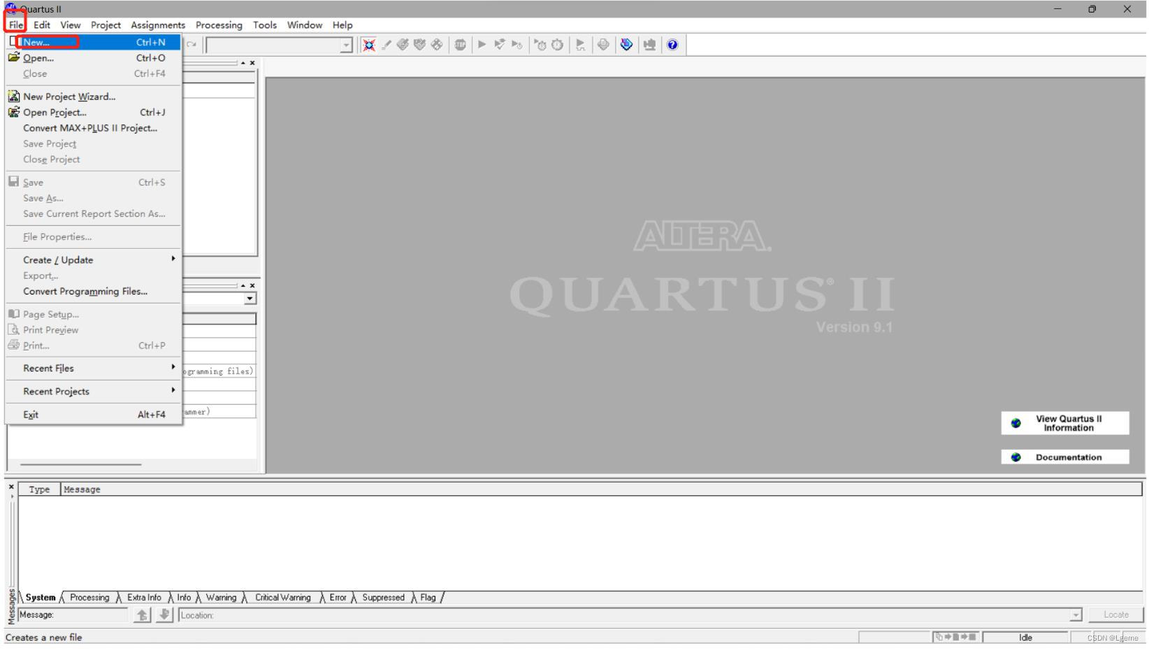
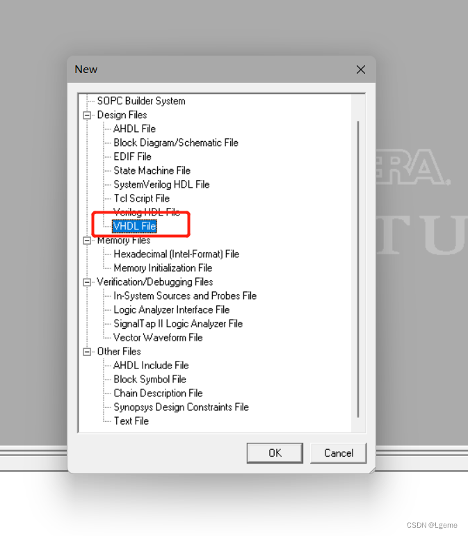
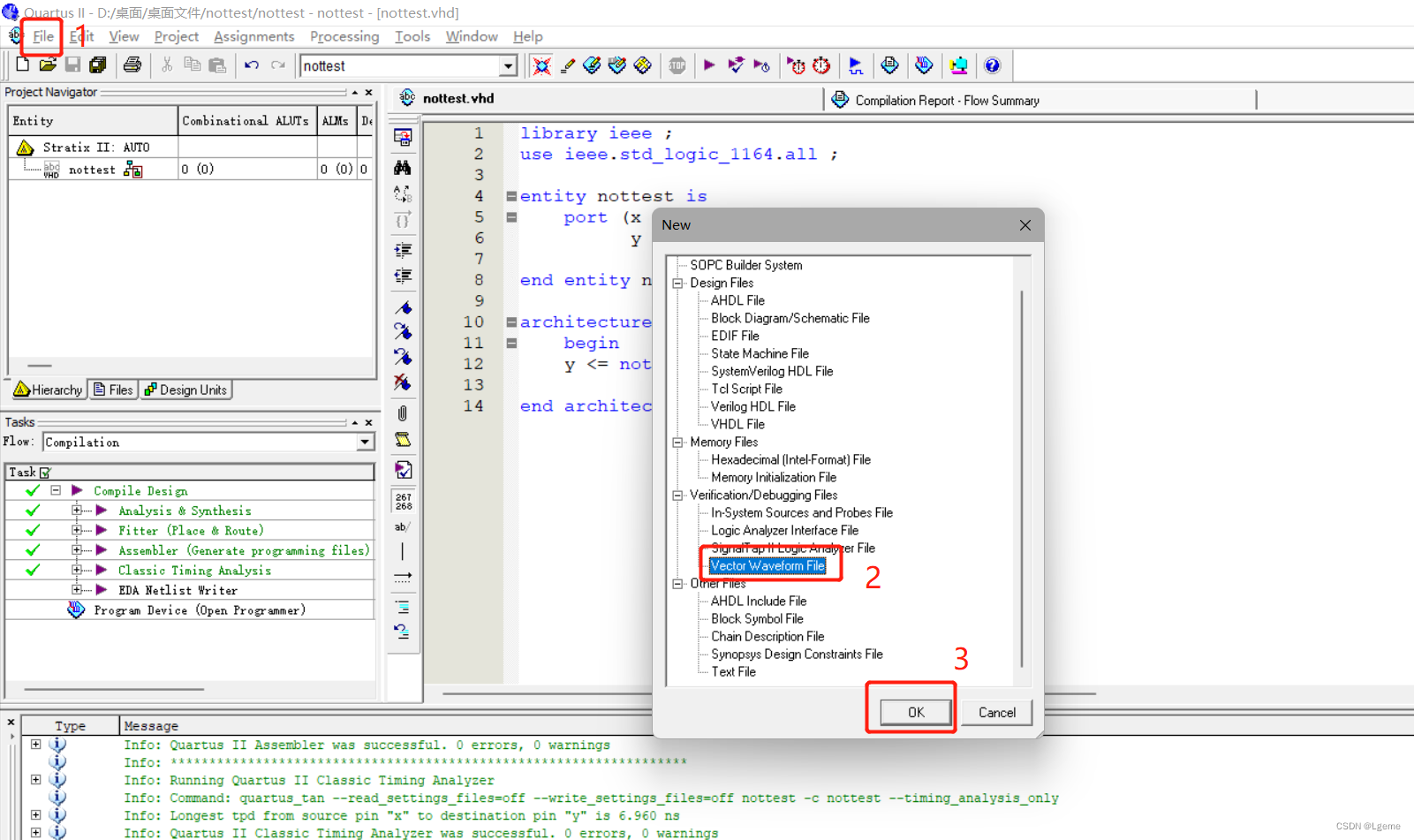
首先打开Quartus II 新建vhdl文件
右侧就是代码编辑界面

本例通过VHDL实现一个简单的非门案例,有利于新手快速入门
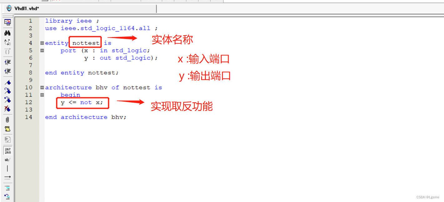
相关量解释
nottest:实体名称
x:输入端口
y:输出端口
bhv:结构体
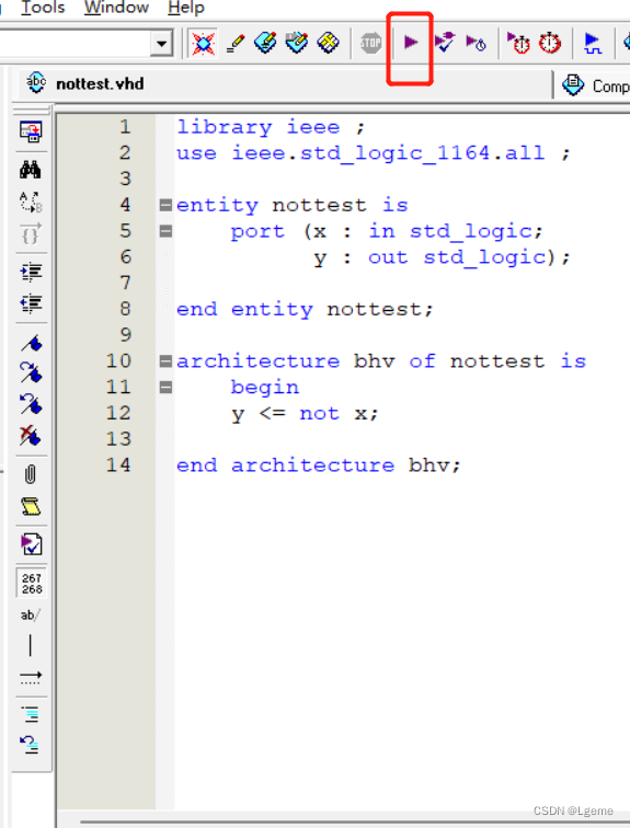
实现代码如下:
library ieee ;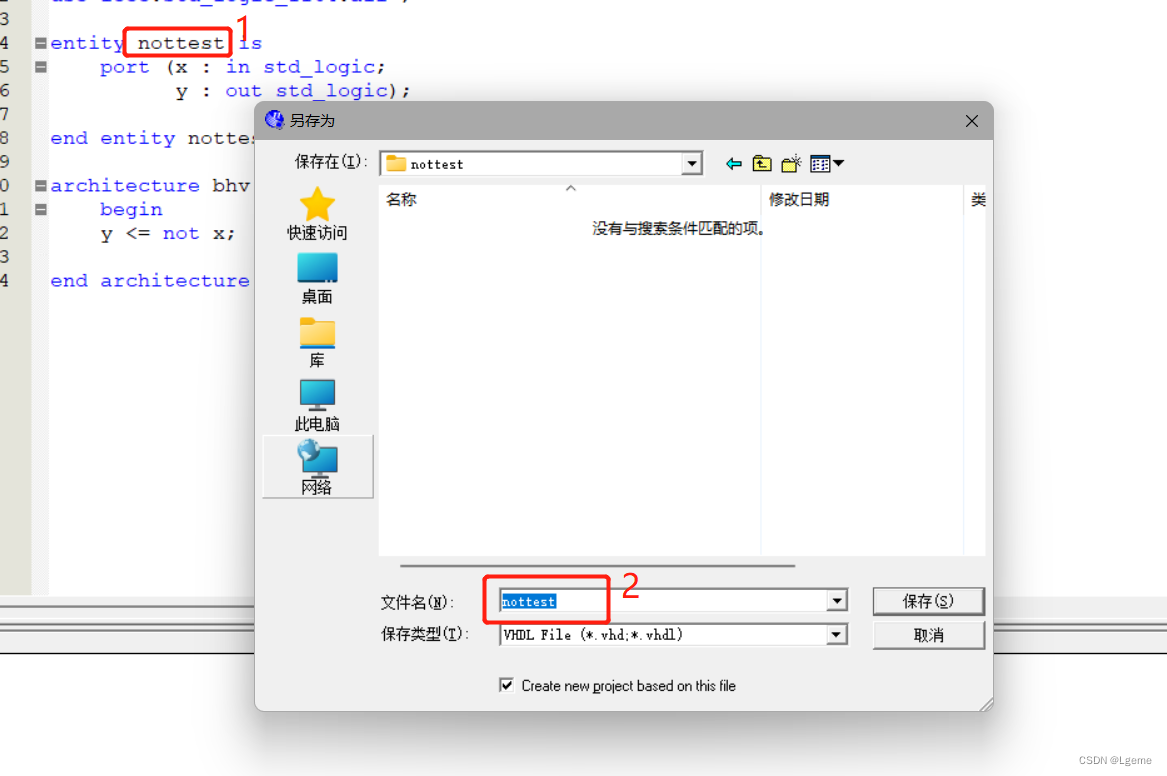
use ieee.std_logic_1164.all ;entity nottest isport (x : in std_logic;y : out std_logic);end entity nottest;architecture bhv of nottest isbegin y <= not x;end architecture bhv;ctrl+s保存文件(注意文件名要和实体名相同否则编译的时候会报错)
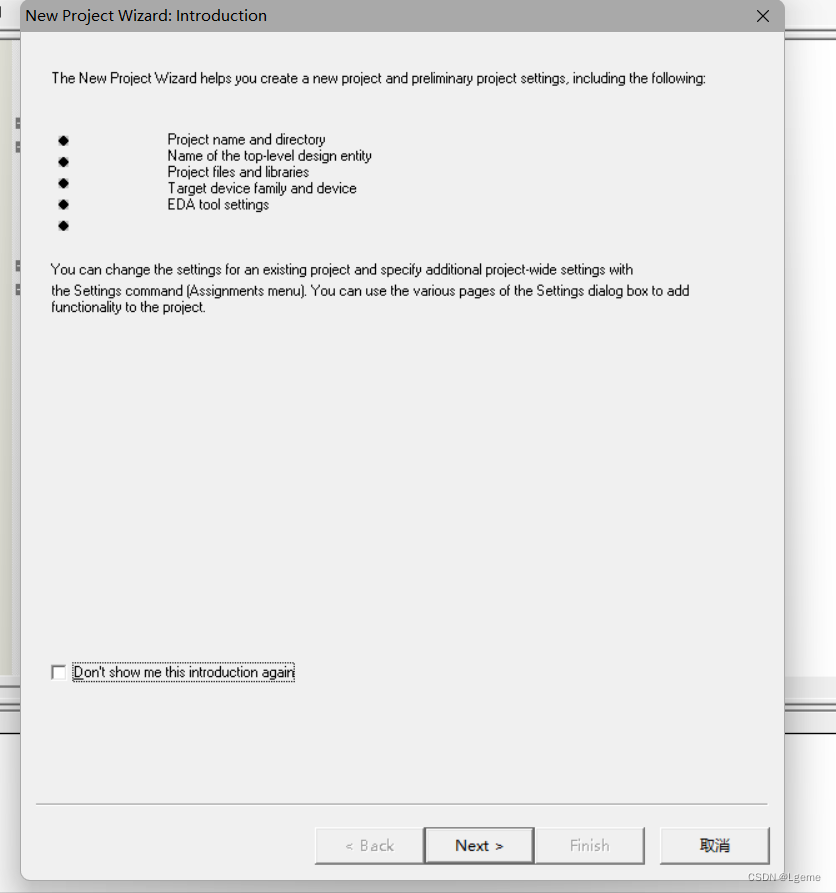
接下来出现工程创建向导界面
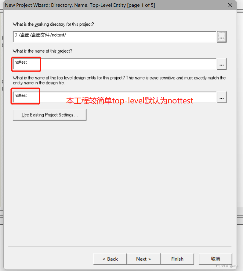
配置工程路径、名称和top-level
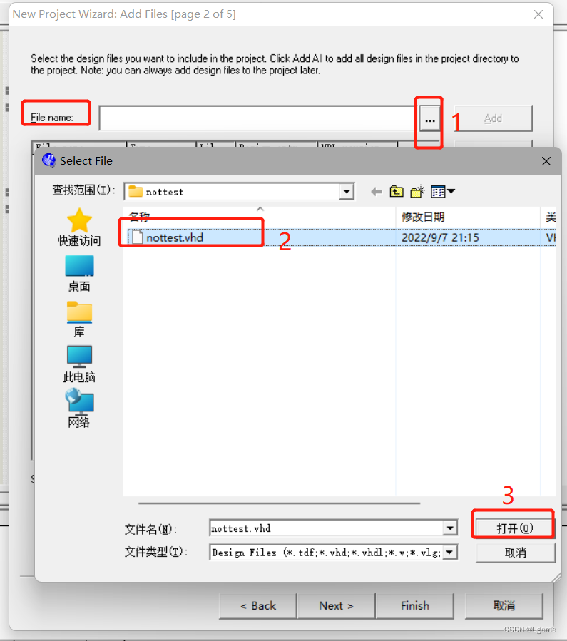
 添加刚才保存的nottest.vhd文件
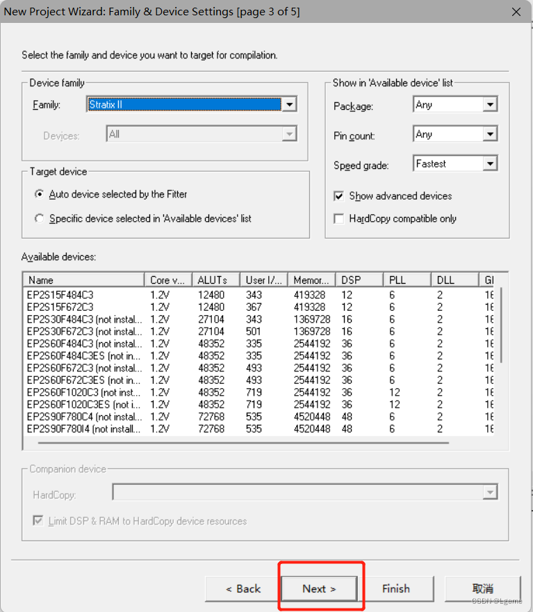
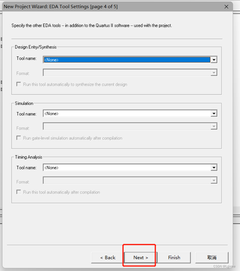
因为此案例没有指定特定的FPGA板子上对应的芯片,所以后面的两页都默认点击next
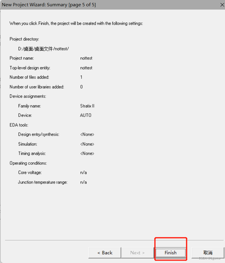
完成工程创建
点击下方图片的紫色图标进行编译
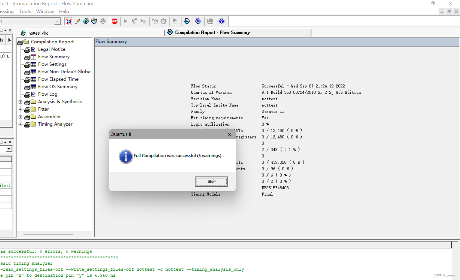
编译成功
二:创建Vector WaveForm File进行波形仿真
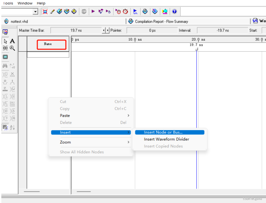
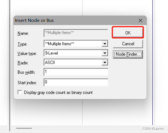
此时还没有添加节点,在name下方空白区域右键进行插入节点
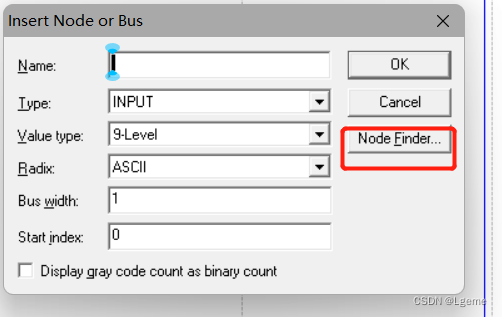
点击Node_Finder添加节点
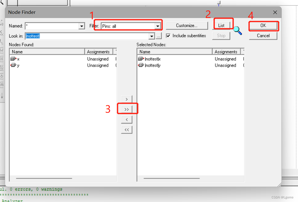
最后点击OK完成节点添加
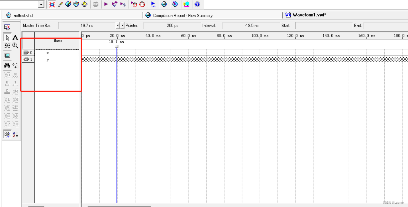
此时波形文件出现了输入、输出节点
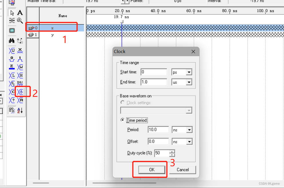
对输入节点X提供时钟波形
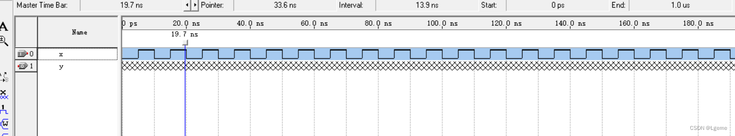
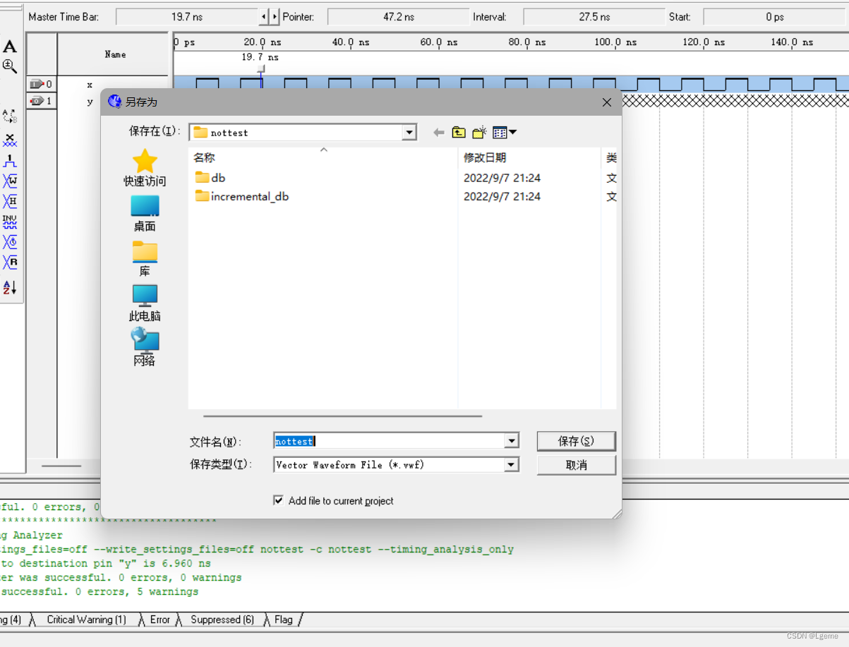
对Waveform1.vmf文件进行保存
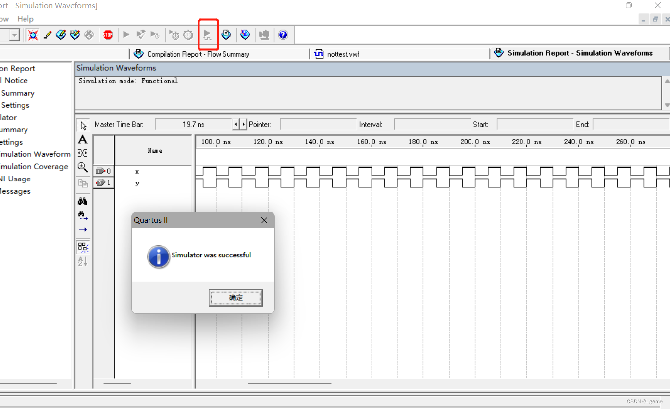
点击下方箭头进行仿真
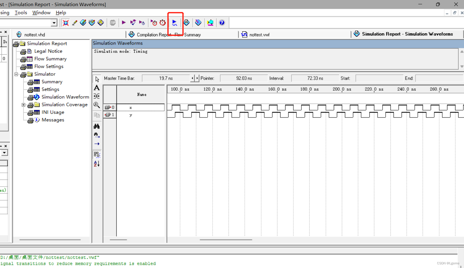
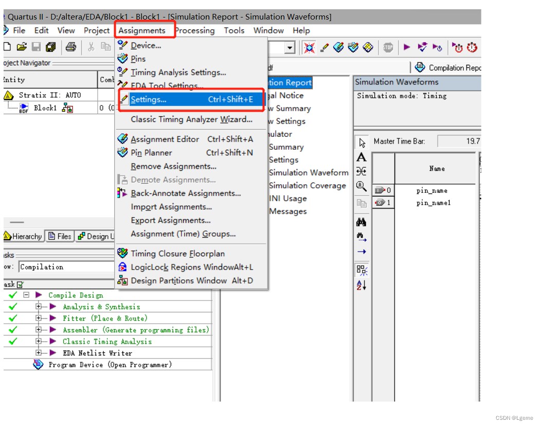
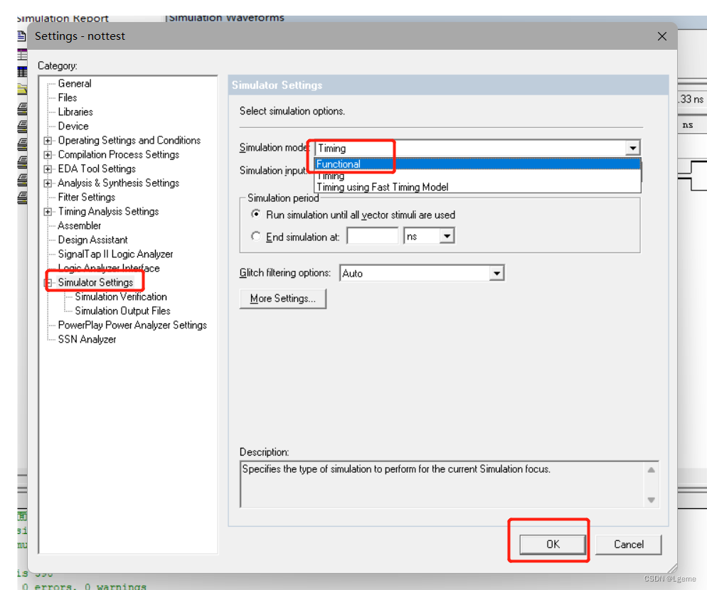
此时y出现了波形但是和非门的效果相差甚远。这时因为本例只是一个简单的组合逻辑门电路不是时序逻辑电路,进入Assignments界面点击Setting下将Simulation mode从Timing改为Functional。(默认的仿真模式是Timing)
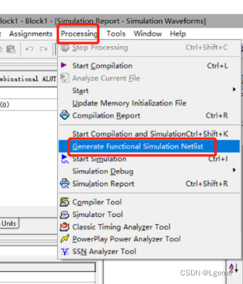
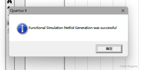
最后点击Processing中的Generate Functional Simulation Netlist生成仿真节点列表
重新点击仿真图标可以得到正常的波形
三:案例扩展
下面我还列举了二选一选择器和四选一选择器的代码,有需要的可以按照上述步骤进行工程创建和仿真练习
二选一选择器代码及仿真波形图:
entity select1of2 is port (a, b, s : in bit;y : out bit);
end entity select1of2;architecture bhv of select1of2 is beginprocess(a,b,s)beginif(s='1') then y<=a; else y<=b;end if;end process;
end architecture bhv;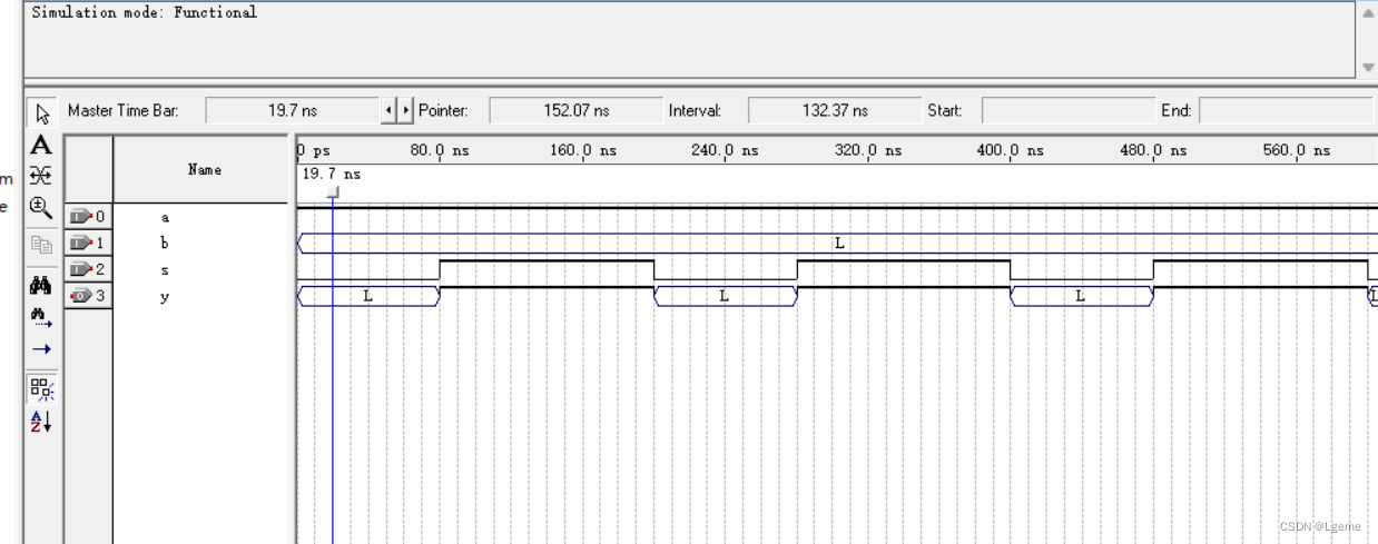
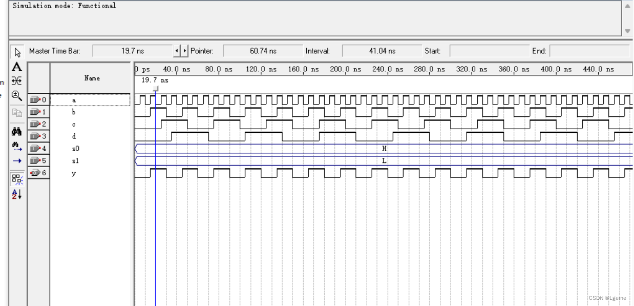
四选一选择器代码及仿真波形图:
library ieee;
use ieee.std_logic_1164.all;entity select1of4 is
port(a, b, c, d, s0, s1 : in std_logic;y  : out std_logic);end entity select1of4;architecture bhv of select1of4 is
signal s : std_logic_vector(1 downto 0);
begin
s <= s1 & s0;process(s)  begin
case (s) iswhen "00" => y <= a;when "01" => y <= b;when "10" => y <= c;when "11" => y <= d;when others => null;end case;
end process;
end architecture bhv;