1.引言
由于最近在学习数据流分析的相关知识,记录一下利用LLVM生成CFG和DFG的学习过程,参考文献和网址放在文章末尾。
2.实验环境
操作系统:Ubuntu 20.04.3 LTS 64bit;
硬件设备:Intel® Celeron(R) CPU N3450 @ 1.10GHz × 4
AMD® Hainan / Mesa Intel® HD Graphics 500 (APL 2)
LLVM 10.0.0-4
Clang version 10.0.0-4ubuntu1
3.实验记录
3.1 实验步骤
1.首先利用LLVM的编译前端Clang将高级语言程序(C/C++)转换成LLVM IR中间表示结果;
2.利用事先写好的分析Pass(分析Pass写好后需要进行重新编译LLVM,然后在LLVM的lib库中生成运行时的库.so文件),具体的CFG生成Pass的伪代码如下所示,主要流程是遍历整个函数,找到基本块然后对每个基本块进行遍历,找到目标操作符,锁定目标操作符的行号上下级信息完成控制流信息的获取;

DFG的分析Pass类似CFG分析Pass,基本步骤一样,但是根据我在网上看到一些调用命令,发现CFG的生成好像可以直接利用LLVM的opt工具获得dot文件,但是DFG的似乎没有,因为本人刚接触这个工具,所以不是很熟悉,知道的朋友可以在评论区补充一下,关于CFG/DFG的分析Pass放在文章的附录部分,有需要的可以自行查看。
3.利用该Pass分析程序的控制流信息和程序调用信息,并通过LLVM的opt工具调用分析Pass生成的.so文件生成.dot文件;
4.由于LLVM没有可视化工具,需要借助第三方可视化平台graphviz,利用其dot文件转化工具将.dot转化为.png或.pdf文件,安装命令如下:
sudo apt-get install -y graphviz-doc libgraphviz-dev graphviz
3.2 实验结果
本文实验程序如下所示:
//file test.c
#include<srdio.h>
int add(int c,int e){return c+e;
}
int main(){int a = 10;int b = a;return add(a,b);
}
首先通过Clang生成LLVM IR文件:
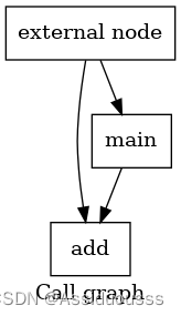
Clang -S -emit-llvm test.c -o test.ll生成调用的控制流图:
opt -dot-callgraph test.ll根据生成的dot文件名称,使用以下命令来生成图片:
dot callgraph.dot -Tpng -o testgraph.png #生成调用图片得到的控制流图如下:
接下来获取函数内部指令调度的命令如下:
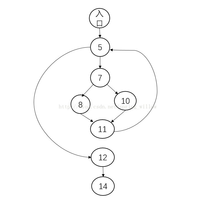
opt -dot-cfg test.ll #生成dot文件运行后,会在当前的文件夹目录下得到一个.dot文件,不同版本的LLVM得到的.dot文件可能不一样,LLVM10.0.0得到的文件名为.main.dot,然后输入以下命令生成图片:
dot .main.dot -Tpng -o cc.png得到以下IR指令的控制流图:

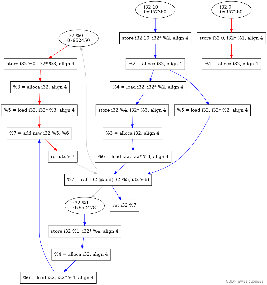
接下来获取程序的DFG图,同样是在程序转换成中间代码LLVM IR的基础上进行操作,首先将自己写好的分析Pass进行编译,生成.so文件放在build文件夹中。使用如下命令:
opt -load /home/lwq/Desktop/LLVM-CFG-DFG-pass-master/CDFG/DFGPass/build/DFG/libLLVMDFG.so -DFGPass<test.ll> /dev/null其中load指令后面为编译后文件所在位置,接下来会得到不同函数的.dot文件,选择all.dot文件,输入以下命令:
dot -Tpng all.dot -o ccc.png则得到下面的DFG图
4.总结
这些简单的CFG/DFG图生成只是博主简单调用了一些相关工具,在此基础上可以进行代码优化和改进,或者写出一些效率更好的Pass,并且由于LLVM安装过程中的编译问题,似乎只有Debug版本的LLVM才可以使用可视化的命令,本来还想利用LLC工具中的llc -view-combine1-dags test.ll输出程序的DAG图,但是本人是直接使用sudo apt install llvm命令下载的LLVM工具,据说是release版本,所以我调用LLC工具的时候发现并没有上述的DAG指令,因此感兴趣的朋友可以自己试试生成DAG图,成功的话可以在评论区告诉一下我。
最后DAGpass分析的程序如下:
#include"graph.h"using namespace llvm;
namespace {struct DFGPass : public ModulePass {public:static char ID;map<string, Graph*> DFGs;map<string, Graph*> CFGs;DFGPass() : ModulePass(ID) {}bool runOnModule(Module &M) override {for (Module::iterator iter_F = M.begin(), FEnd = M.end(); iter_F != FEnd; ++iter_F) {Function *F = &*iter_F;Graph* control_flow_G = new Graph(F);Graph* data_flow_G = new Graph(F);// F->viewCFG();DFGs.insert(pair<string, Graph*>(F->getName().str(), data_flow_G));CFGs.insert(pair<string, Graph*>(F->getName().str(), control_flow_G));control_flow_G->head.push_back(pair<Value*, Value*>(&*(F->begin())->begin(), &*(F->begin())->begin()));for (Function::iterator BB = F->begin(), BEnd = F->end(); BB != BEnd; ++BB) {BasicBlock *curBB = &*BB;for (BasicBlock::iterator II = curBB->begin(), IEnd = curBB->end(); II != IEnd; ++II) {Instruction* curII = &*II;switch (curII->getOpcode()){// for the case of load operation, we should save the value of itcase llvm::Instruction::Load:{LoadInst* linst = dyn_cast<LoadInst>(curII);Value* loadValPtr = linst->getPointerOperand();insert(data_flow_G, pair<Value*, Value*>(loadValPtr, curII));break;}// for the case of store operation, both of the pointer and value should be recodedcase llvm::Instruction::Store: {StoreInst* sinst = dyn_cast<StoreInst>(curII);Value* storeValPtr = sinst->getPointerOperand();Value* storeVal = sinst->getValueOperand();insert(data_flow_G, pair<Value*, Value*>(storeVal, curII));insert(data_flow_G, pair<Value*, Value*>(curII, storeValPtr));data_flow_G->head.push_back(pair<Value*, Value*>(storeValPtr, storeVal));break;}case llvm::Instruction::Call: {CallInst* cinst = dyn_cast<CallInst>(curII);string f_name = cinst->getCalledFunction()->getName();for(auto iter = DFGs[f_name]->F->arg_begin(), iter_end = DFGs[f_name]->F->arg_end(); iter != iter_end; iter++){data_flow_G->link.push_back(pair<Value*, Value*>(cinst, iter));errs()<<*cinst<<cinst<<"->"<<*iter<<iter<<"\n";// insert(data_flow_G, pair<Value*, Value*>(cinst, iter));}if(!DFGs[f_name]->F->doesNotReturn()){Value* ret_i = &*(--(--DFGs[f_name]->F->end())->end());data_flow_G->link.push_back(pair<Value*, Value*>(ret_i, cinst));// insert(data_flow_G, pair<Value*, Value*>(ret_i, cinst));}}// for other operation, we get all the operand point to the current instructiondefault: {for (Instruction::op_iterator op = curII->op_begin(), opEnd = curII->op_end(); op != opEnd; ++op){Instruction* tempIns;if (dyn_cast<Instruction>(*op)){insert(data_flow_G, pair<Value*, Value*>(op->get(), curII));}}break;}}BasicBlock::iterator next = II;++next;if (next != IEnd) {insert(control_flow_G, pair<Value*, Value*>(curII, &*next));}}Instruction* terminator = curBB->getTerminator();for (BasicBlock* sucBB : successors(curBB)) {Instruction* first = &*(sucBB->begin());insert(control_flow_G, pair<Value*, Value*>(terminator, first));}}writeFileByGraph(F);}// NOTWITHCFHG indicate the fianl graph represents no CFG informationwriteFileByGraphGloble(NOTWITHCFG);errs()<<"end\n";return false;}void DFS_plot(Edge* v, Graph* G, raw_fd_ostream& file){Edge* p = v;while (p){if (mark.find(pair<int, int>(p->v_from, p->v_to)) == mark.end()) {mark.insert(pair<int, int>(p->v_from, p->v_to));file << "\tNode" << G->v[p->v_from]->va << " -> Node" << G->v[p->v_to]->va << "\n";DFS_plot(G->v[p->v_to]->first_out, G, file);}p = p->out_edge;}}void writeFileByGraph(Function *F){std::error_code error;enum sys::fs::OpenFlags F_None;StringRef fileName(F->getName().str() + ".dot");raw_fd_ostream file(fileName, error, F_None);Graph* data_flow_G =  DFGs[F->getName().str()];Graph* control_flow_G = CFGs[F->getName().str()];file << "digraph \"DFG for'" + F->getName() + "\' function\" {\n";for (auto node_iter = DFGs[F->getName()]->v.begin(), node_end = DFGs[F->getName()]->v.end(); node_iter != node_end; ++node_iter) {Value* p = (*node_iter)->va;if(isa<Instruction>(*p)){file << "\tNode" << p << "[shape=record, label=\"" << *p << "\"];\n";}else{file << "\tNode" << p << "[shape=ellipse, label=\"" << *p << "\\l" << p << "\"];\n";}}// plot the instruction flow edgemark.clear();for(auto iter = control_flow_G->head.begin(), iter_end = control_flow_G->head.end(); iter != iter_end; iter++){DFS_plot(control_flow_G->v[find(control_flow_G->v, iter->second)]->first_out, control_flow_G, file);}// plot the data flow edgefile << "edge [color=red]" << "\n";mark.clear();for(auto iter = data_flow_G->head.begin(), iter_end = data_flow_G->head.end(); iter != iter_end; iter++){DFS_plot(data_flow_G->v[find(data_flow_G->v, iter->second)]->first_out, data_flow_G, file);}file << "}\n";file.close();}void writeFileByGraphGloble(Mode m){std::error_code error;enum sys::fs::OpenFlags F_None;StringRef fileName("all.dot");raw_fd_ostream file(fileName, error, F_None);file << "digraph \"DFG for all\" {\n";for(auto F_iter = DFGs.begin(), F_iter_end = DFGs.end(); F_iter != F_iter_end; F_iter++){Graph* data_flow_G =  DFGs[F_iter->first];Graph* control_flow_G = CFGs[F_iter->first];auto nodes = F_iter->second->v;for (auto node_iter = nodes.begin(), node_end =  nodes.end(); node_iter != node_end; ++node_iter) {Value* p = (*node_iter)->va;if(isa<Instruction>(*p)){file << "\tNode" << p << "[shape=record, label=\"" << *p << "\"];\n";}else{file << "\tNode" << p << "[shape=ellipse, label=\"" << *p << "\\l" << p << "\"];\n";}}// plot the instruction flow edgeif(m != NOTWITHCFG){file << "edge [color=black]" << "\n";mark.clear();for(auto iter = control_flow_G->head.begin(), iter_end = control_flow_G->head.end(); iter != iter_end; iter++){DFS_plot(control_flow_G->v[find(control_flow_G->v, iter->second)]->first_out, control_flow_G, file);}}// plot the data flow edgevector<string> color_set = {"red", "blue", "cyan", "orange", "yellow"};mark.clear();int count = 0;for(auto iter = data_flow_G->head.begin(), iter_end = data_flow_G->head.end(); iter != iter_end; iter++){file << "edge [color=" << color_set[count++] << "]" << "\n";DFS_plot(data_flow_G->v[find(data_flow_G->v, iter->second)]->first_out, data_flow_G, file);}for(auto iter = data_flow_G->link.begin(), iter_end = data_flow_G->link.end(); iter != iter_end; iter++){file << "edge [color=grey]" << "\n";file << "\tNode" << iter->first << " -> Node" << iter->second << "\n";errs() << *iter->first << *iter->second << "\n";}}file << "}\n";file.close();}};
}char DFGPass::ID = 0;
static RegisterPass<DFGPass> X("DFGPass", "DFG Pass Analyse",false, false
);
5.参考
在LLVM中可视化代码结构_梦在哪里的博客-CSDN博客_llvm 可视化
LLVM CFG控制流图可视化_ronnie88597的博客-CSDN博客_llvm 控制流图
[1]赵德硕. 面向LLVM编译器的线程级推测执行模型的研究[D].西北农林科技大学,2021.DOI:10.27409/d.cnki.gxbnu.2021.001026.