写了markdown 上传,公式都乱码,无果,截图上传吧
目录
1. hector 原理解析
1.4 多重分辨率地图
2.代码框架
2.1 回调函数
2.2 更新
3. 扫描匹配
3.1 多分辨率匹配
3.2 matchData_2
3.3 scan_match_3
3.4 迭代计算函数
3.5 hession 矩阵H 求解
3.6 双线性插值计算得分与梯度
4. 地图更新
4.1多分辨率地图
4.2用激光数据和位姿更新地图
4.3 应用分层scan更新地图
4.4 实际地图更新函数
4.5 应用bresenham 画线
4.5.1 bresenham2D()
4.5.2 bresenhamCellFree() & bresenhamCellOcc()
4.6占用栅格的更新
5. 运行效果
6. 优缺点总结与思考
6.1. 优点
6.2. 缺点
6.3. 思考
6.4. 改进点
7. 参考链接
1. hector 原理解析
Hector SLAM扫描匹配原理解析
扫描匹配就是使用当前帧与已有地图数据构建误差函数,并用Gauss_Newton法得到最优解和偏差量。其工作是实现激光点到栅格地图的转换,t时刻所有的激光点都能变换到栅格地图中,也就意味着匹配成功。


------引自《视觉salm14讲》


图1. 激光扫描端点在各个坐标系中的坐标表示


1.4 多重分辨率地图
任何基于爬山或坡度的方法都具有固有的风险,即陷入局部极小值。由于提出的方法基于梯度上升,因此也有可能陷入局部极小值。通过使用类似于计算机视觉中使用的图像金字塔方法的多分辨率地图表示,可以缓解该问题。在我们的方法中,我们可以选择使用多个占用栅格图,每个较粗的地图的分辨率是前一个的一半。但是,无法通过应用高斯滤波和下采样来从单个高分辨率地图生成多个地图级别,就像在图像处理中通常这样做的那样。取而代之的是,将不同的地图保留在内存中,并使用对齐过程生成的姿态估计值同时进行更新。这种生成方法可确保地图在各个比例尺上保持一致,同时避免了高代价的下采样操作。扫描对齐过程类似于上文中介绍的方法,从最粗糙的地图级别开始,然后将得到的估计姿势用作下一个级别的开始估计。这样带来的一个积极副作用是可以立即使用粗粒度的地图,例如可以用于路径规划。

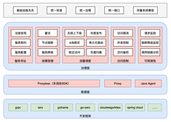
2.代码框架

图片引自Hector_slam源码框架分析_blue@sky的博客-CSDN博客_hector slam ,如有侵权烦请联系删除。
算法核心代码主要在hector_slam的src和头文件中;
几个主要函数,如上图所示,实际的牛顿高斯实现和地图更新均在OccGridMapUtil.h中
2.1 回调函数
回调函数首先进行雷达数据格式转换
然后扫描匹配与地图更新。
/*** 激光数据处理回调函数,将ros数据格式转换为算法中的格式,并转换成地图尺度,交由slamProcessor处理。* 算法中所有的计算都是在地图尺度下进行。  * 激光数据处理回调函数,将ros数据格式转换未算法中的格式,并转换成地图尺度,交由slamprocessor处理。* 算法中所有的计算都是在地图尺度下进行。*/
void HectorMappingRos::scanCallback(const sensor_msgs::LaserScan &scan)
{start_time_ = std::chrono::steady_clock::now();ros::WallTime startTime = ros::WallTime::now();// 将 scan 转换成 点云格式//将scan 转换成点云格式projector_.projectLaser(scan, laser_point_cloud_, 30.0);Eigen::Vector3f startEstimate(Eigen::Vector3f::Zero());// 将雷达数据的点云格式 更改成 hector 内部的数据格式if (rosPointCloudToDataContainer(laser_point_cloud_, laserTransform_, laserScanContainer, slamProcessor->getScaleToMap())){// 首先获取上一帧的位姿,作为初值,如果是第一帧,在slamprocessor 实例化的时候map-reset 重置了位姿。startEstimate = slamProcessor->getLastScanMatchPose();// 进入扫描匹配与地图更新//核心工作 扫描匹配和地图更新,输入为当前帧scan与上一帧位姿slamProcessor->update(laserScanContainer, startEstimate);}end_time_ = std::chrono::steady_clock::now();time_used_ = std::chrono::duration_cast<std::chrono::duration<double>>(end_time_ - start_time_);std::cout << "数据转换与扫描匹配用时: " << time_used_.count() << " 秒。" << std::endl;if (p_timing_output_){ros::WallDuration duration = ros::WallTime::now() - startTime;ROS_INFO("HectorSLAM Iter took: %f milliseconds", duration.toSec() * 1000.0f);}// 更新存储的位姿, 这里的位姿是 base_link 在 map 下的位姿poseInfoContainer_.update(slamProcessor->getLastScanMatchPose(), slamProcessor->getLastScanMatchCovariance(), scan.header.stamp, p_map_frame_);if (pub_map_to_baselink_tf_){// pub map -> odom -> base_link tfif (p_pub_map_odom_transform_){tfB_->sendTransform(tf::StampedTransform(map_to_odom_, scan.header.stamp, p_map_frame_, p_odom_frame_));tfB_->sendTransform(tf::StampedTransform(poseInfoContainer_.getTfTransform(), scan.header.stamp, p_odom_frame_, p_tf_map_scanmatch_transform_frame_name_));// tfB_->sendTransform(tf::StampedTransform(map_to_odom_, ros::Time::now(), p_map_frame_, p_odom_frame_));// tfB_->sendTransform(tf::StampedTransform(poseInfoContainer_.getTfTransform(), ros::Time::now(), p_odom_frame_, p_tf_map_scanmatch_transform_frame_name_));}// pub map -> base_link tfelse{tfB_->sendTransform(tf::StampedTransform(poseInfoContainer_.getTfTransform(), scan.header.stamp, p_map_frame_, p_tf_map_scanmatch_transform_frame_name_));}}// 发布 odom topicif (p_pub_odometry_){nav_msgs::Odometry tmp;tmp.pose = poseInfoContainer_.getPoseWithCovarianceStamped().pose;tmp.header = poseInfoContainer_.getPoseWithCovarianceStamped().header;// tmp.header.stamp = ros::Time::now();tmp.child_frame_id = p_base_frame_;odometryPublisher_.publish(tmp);}end_time_ = std::chrono::steady_clock::now();time_used_ = std::chrono::duration_cast<std::chrono::duration<double>>(end_time_ - start_time_);std::cout << "执行一次回调用时: " << time_used_.count() << " 秒。" << std::endl;
}
2.2 更新
核心是slamProcessor->update(laserScanContainer, startEstimate);
update() 函数位于 HectorSlamProcessor.h中.
将scan_match与地图更新分成了2步进行,将分别在第3节与第4节展开说明。
scan_match是调用mapRep->matchData()函数,返回了当前scan在与地图进行扫描匹配后的地图坐标系下的位姿.
之后调用了updateByScan()进行了地图的更新;详细解释在第4节展开
3. 扫描匹配
3.1 多分辨率匹配
mapRep->matchData 位于MapRepMultiMap.h中
如果有三层多分辨率地图,则首先使用setFrom 将激光数据进行尺度变化,对每个原始数据乘以1/(2的
次方),n 取 2、1、0。分别用不同分辨率的地图就行扫描匹配已达到求解更准确。
也就是先在粗分辨率地图上匹配,得出结果再传入更细分辨率地图匹配,最终得到一个更精确的估计。
/*** 地图匹配,通过多分辨率地图求解当前激光帧的pose。* @param beginEstimateWorld* @param dataContainer* @param covMatrix* @return*/virtual Eigen::Vector3f matchData(const Eigen::Vector3f &beginEstimateWorld, const DataContainer &dataContainer, Eigen::Matrix3f &covMatrix){size_t size = mapContainer.size();Eigen::Vector3f tmp(beginEstimateWorld);/// coarse to fine 的pose求精过程,i层的求解结果作为i-1层的求解初始值。for (int index = size - 1; index >= 0; --index){//std::cout << " m " << i;if (index == 0){tmp = (mapContainer[index].matchData(tmp, dataContainer, covMatrix, 5)); /// 输入数据dataContainer 对应 mapContainer[0]}else{// 根据地图层数对原始激光数据坐标进行缩小,得到对应图层尺寸的激光数据dataContainers[index - 1].setFrom(dataContainer, static_cast<float>(1.0 / pow(2.0, static_cast<double>(index))));tmp = (mapContainer[index].matchData(tmp, dataContainers[index - 1], covMatrix, 3));/// dataContainers[i]对应mapContainer[i+1]}}return tmp;}3.2 matchData_2
maprep中的实际调用match_data 在MapProcContainer.h中,实际,只是过度,将对应分辨率地图传入实际matchData 所在类中
/*** 给定位姿初值,估计当前scan在当前图层中的位姿 ---- 位姿为世界系下的pose 、 dataContainer应与当前图层尺度匹配* @param beginEstimateWorld 世界系下的位姿* @param dataContainer 激光数据* @param covMatrix scan-match的不确定性 -- 协方差矩阵* @param maxIterations 最大的迭代次数* @return*/Eigen::Vector3f matchData(const Eigen::Vector3f &beginEstimateWorld, const DataContainer &dataContainer, Eigen::Matrix3f &covMatrix, int maxIterations){return scanMatcher->matchData(beginEstimateWorld, *gridMapUtil, dataContainer, covMatrix, maxIterations);}3.3 scan_match_3
第三个 matchData() 位于hector_mapping/matcher/ScanMatcher.h 中.
这回终于是真正进行扫描匹配的地方了。
首先说一下hector world坐标系与hector map坐标系
之前说的这个初始位姿一直都是world坐标系下的坐标,Hector中认为实际物理坐标表示成的坐标为world坐标,以左上角为原点的.
而hector map坐标就是用 world坐标再除以地图的分辨率0.05(也就是乘以20),再加上map坐标系的原点 得到的.也就是像素坐标.
这段代码先将给定的初始位姿转换成Hector的map坐标系下的像素坐标.
之后调用了 estimateTransformationLogLh() 进行计算位姿,之后又通过多次调用这个函数使结果更加准确.
求解的过程就在 estimateTransformationLogLh() 里.
这里的H矩阵是这个类的私有变量,代表hessian, 也就是要返回的协方差矩阵.
然后,将estimate从地图坐标系下转到world坐标系下,再返回。
/*** 实际进行位姿估计的函数* @param beginEstimateWorld 位姿初值* @param gridMapUtil 网格地图工具,这里主要是用来做坐标变换* @param dataContainer 激光数据* @param covMatrix 协方差矩阵* @param maxIterations 最大迭代次数* @return*/Eigen::Vector3f matchData(const Eigen::Vector3f &beginEstimateWorld,ConcreteOccGridMapUtil &gridMapUtil, const DataContainer &dataContainer,Eigen::Matrix3f &covMatrix, int maxIterations){if (dataContainer.getSize() != 0){// 1. 初始pose转换为地图尺度下的pose --仿射变换,包括位姿的尺度和偏移,旋转在 X Y 同尺度变化时保持不变Eigen::Vector3f beginEstimateMap(gridMapUtil.getMapCoordsPose(beginEstimateWorld));Eigen::Vector3f estimate(beginEstimateMap);// 2. 第一次迭代estimateTransformationLogLh(estimate, gridMapUtil, dataContainer);int numIter = maxIterations;/** 3. 多次迭代求解 **/for (int i = 0; i < numIter; ++i){estimateTransformationLogLh(estimate, gridMapUtil, dataContainer);}// 角度正则化estimate[2] = util::normalize_angle(estimate[2]);covMatrix = Eigen::Matrix3f::Zero();//covMatrix.block<2,2>(0,0) = (H.block<2,2>(0,0).inverse());//covMatrix.block<2,2>(0,0) = (H.block<2,2>(0,0));// 使用Hessian矩阵近似协方差矩阵covMatrix = H;// 结果转换回物理坐标系下 -- 转换回实际尺度return gridMapUtil.getWorldCoordsPose(estimate);}return beginEstimateWorld;}3.4 迭代计算函数
首先,这个函数通过getCompleteHessianDerivs() 计算出了协方差矩阵H , 以及 dTr向量.
之后,通过高斯牛顿法最终推倒出的求根公式: H的逆 乘以 dtr 求出 先验位姿与后验位姿间的增量. 也就是 X = H.inverse() * dTr --> H * X = dTr
最后再将这个增量加上之前的预测值,得到匹配之后的位姿.
/*** 高斯牛顿估计位姿* @param estimate 位姿初始值* @param gridMapUtil 网格地图相关计算工具* @param dataPoints 激光数据* @return 提示是否有解 --- 貌似没用上*/bool estimateTransformationLogLh(Eigen::Vector3f &estimate,ConcreteOccGridMapUtil &gridMapUtil,const DataContainer &dataPoints){/** 核心函数,计算H矩阵和dTr向量(b列向量)---- occGridMapUtil.h 中 **/gridMapUtil.getCompleteHessianDerivs(estimate, dataPoints, H, dTr);//std::cout << "\nH\n" << H << "\n";//std::cout << "\ndTr\n" << dTr << "\n";// 判断H是否可逆, 判断增量非0,避免无用计算if ((H(0, 0) != 0.0f) && (H(1, 1) != 0.0f)){// 求解位姿增量Eigen::Vector3f searchDir(H.inverse() * dTr);// 角度增量不能太大if (searchDir[2] > 0.2f){searchDir[2] = 0.2f;std::cout << "SearchDir angle change too large\n";}else if (searchDir[2] < -0.2f){searchDir[2] = -0.2f;std::cout << "SearchDir angle change too large\n";}// 更新估计值 --- 结果在地图尺度下updateEstimatedPose(estimate, searchDir);return true;}return false;}
3.5 hession 矩阵H 求解
getCompleteHessianDerivs() 函数 位于hector_mapping/map/OccGridMapUtil.h中
代码根据第2节中的公式一一对应,很容易看懂。
/*** 使用当前pose投影dataPoints到地图,计算出 H 矩阵 b列向量, 理论部分详见Hector论文: 《A Flexible and Scalable SLAM System with Full 3D Motion Estimation》.* 位置估计初始值,或者当前值,对应尺度的激光点坐标* @param pose 地图系上的位姿* @param dataPoints 已转换为地图尺度的激光点数据* @param H 需要计算的 H矩阵* @param dTr 需要计算的 g列向量*/void getCompleteHessianDerivs(const Eigen::Vector3f &pose,const DataContainer &dataPoints,Eigen::Matrix3f &H,Eigen::Vector3f &dTr){int size = dataPoints.getSize();// 获取变换矩阵 //仿射变换,获取poseEigen::Affine2f transform(getTransformForState(pose));float sinRot = sin(pose[2]);float cosRot = cos(pose[2]);H = Eigen::Matrix3f::Zero();dTr = Eigen::Vector3f::Zero();// 按照公式计算H、bfor (int i = 0; i < size; ++i){// 地图尺度下的激光坐标系下的激光点坐标const Eigen::Vector2f &currPoint(dataPoints.getVecEntry(i));// 将激光点坐标转换到地图系上, 通过双线性插值计算栅格概率//转换为地图坐标// transformedPointData[0]--通过插值得到的栅格值// transformedPointData[1]--栅格值x方向的梯度// transformedPointData[2]--栅格值y方向的梯度Eigen::Vector3f transformedPointData(interpMapValueWithDerivatives(transform * currPoint));// 目标函数f(x) (1-M(Pm))float funVal = 1.0f - transformedPointData[0];// 计算g列向量的 x 与 y 方向的值dTr[0] += transformedPointData[1] * funVal;dTr[1] += transformedPointData[2] * funVal;// 根据公式计算float rotDeriv = ((-sinRot * currPoint.x() - cosRot * currPoint.y()) * transformedPointData[1] +(cosRot * currPoint.x() - sinRot * currPoint.y()) * transformedPointData[2]);// 计算g列向量的 角度 的值dTr[2] += rotDeriv * funVal;// 计算 hessian 矩阵H(0, 0) += util::sqr(transformedPointData[1]);H(1, 1) += util::sqr(transformedPointData[2]);H(2, 2) += util::sqr(rotDeriv);H(0, 1) += transformedPointData[1] * transformedPointData[2];H(0, 2) += transformedPointData[1] * rotDeriv;H(1, 2) += transformedPointData[2] * rotDeriv;}// H是对称矩阵,只算上三角就行, 减少计算量。//对称矩阵,只算上三角,下三角填充即可H(1, 0) = H(0, 1);H(2, 0) = H(0, 2);H(2, 1) = H(1, 2);}3.6 双线性插值计算得分与梯度
该函数在3.5中调用,位于/hector_mapping/map/OccGridMapUtil.h 中
取相邻4个点栅格值时候用到了cache函数,主要目的是避免单次scan重复访问同一网格时带来的重复概率计算
/*** 双线性插值计算网格中任一点的得分(占据概率)以及该点处的梯度* 双线性插值计算网格中任一点的占用概率,以及该点的梯度并返回。* @param coords 激光点地图坐标* @return ret(0) 是网格值 , ret(1) 是栅格值在x方向的导数 , ret(2)是栅格值在y方向的导数*/Eigen::Vector3f interpMapValueWithDerivatives(const Eigen::Vector2f &coords){// 检查coords坐标是否是在地图坐标范围内//激光点坐标是否在地图范围内,如果超过则返回0 值也就是不做计算。if (concreteGridMap->pointOutOfMapBounds(coords)){return Eigen::Vector3f(0.0f, 0.0f, 0.0f);}// 对坐标进行向下取整,即得到坐标(x0,y0)//坐标向下取整,对应栅格索引,Eigen::Vector2i indMin(coords.cast<int>());// 得到双线性插值的因子// | x | | x0 | | x-x0 |// | | - | | = | |// | y | | y0 | | y-y0 |Eigen::Vector2f factors(coords - indMin.cast<float>());// 获得地图的X方向最大边界int sizeX = concreteGridMap->getSizeX();// 计算(x0, y0)点的网格索引值int index = indMin[1] * sizeX + indMin[0]; // 下边这取4个点的栅格值,感觉就是导致hector大地图后计算变慢的原因/** 首先判断cache中该地图点在本次scan中是否被访问过,若有则直接取值;没有则立马计算概率值并更新到cache **//** 这个cache的作用是,避免单次scan重复访问同一网格时带来的重复概率计算。地图更新后,网格logocc改变,cache数据就会无效。 **//** 但是这种方式内存开销太大..相当于同时维护两份地图,使用 hash map 是不是会更合适些 **/if (!cacheMethod.containsCachedData(index, intensities[0])){intensities[0] = getUnfilteredGridPoint(index); // 得到M(P00),P00(x0,y0)cacheMethod.cacheData(index, intensities[0]);}++index;if (!cacheMethod.containsCachedData(index, intensities[1])){intensities[1] = getUnfilteredGridPoint(index);cacheMethod.cacheData(index, intensities[1]);}index += sizeX - 1;if (!cacheMethod.containsCachedData(index, intensities[2])){intensities[2] = getUnfilteredGridPoint(index);cacheMethod.cacheData(index, intensities[2]);}++index;if (!cacheMethod.containsCachedData(index, intensities[3])){intensities[3] = getUnfilteredGridPoint(index);cacheMethod.cacheData(index, intensities[3]);}float dx1 = intensities[0] - intensities[1]; // 求得(M(P00) - M(P10))的值float dx2 = intensities[2] - intensities[3]; // 求得(M(P01) - M(P11))的值float dy1 = intensities[0] - intensities[2]; // 求得(M(P00) - M(P01))的值float dy2 = intensities[1] - intensities[3]; // 求得(M(P10) - M(P11))的值// 得到双线性插值的因子,注意x0+1=x1,y0+1=y1,则// | x-x0 | | 1-x+x0 | | x1-x |// 1 - | | = | | = | |// | y-y0 | | 1-y+y0 | | y1-x |float xFacInv = (1.0f - factors[0]); // 求得(x1-x)的值float yFacInv = (1.0f - factors[1]); // 求得(y1-y)的值// y-y0 | x-x0 x1-x | y1-y | x-x0 x1-x |// M(Pm) = ------|------ M(P11) + ------ M(P01)| + ------|------ M(P10) + ------ M(P00)|// y1-y0| x1-x0 x1-x0 | y1-y0| x1-x0 x1-x0 |// 注意:此处y1-y0=x1-x0=1,那么对应函数返回值,可以写成// M(Pm) = (M(P00) * (x1-x) + M(P10) * (x-x0)) * (y1-y) + (M(P01) * (x1-x) + M(P11) * (x-x0)) * (y-y0)// d(M(Pm)) y-y0 | | y1-y | |// ---------- = ------| M(P11) - M(P01)| + ------| M(P10) - M(P00)|// dx y1-y0| | y1-y0| |// 同理,化简可得 d(M(Pm))/dx = -((M(P00) - M(P10)) * (y1-y) + (M(P01) - M(P11)) * (y-y0))// 同样地,也有 d(M(Pm))/dy = -((M(P00) - M(P01)) * (x1-x) + (M(P10) - M(P11)) * (x-x0))// 计算网格值,计算梯度 --- 原版这里的dx、dy的计算有错误,已经改过来了return Eigen::Vector3f(((intensities[0] * xFacInv + intensities[1] * factors[0]) * (yFacInv)) +((intensities[2] * xFacInv + intensities[3] * factors[0]) * (factors[1])),-((dx1 * yFacInv) + (dx2 * factors[1])),-((dy1 * xFacInv) + (dy2 * factors[0]))// -((dx1 * xFacInv) + (dx2 * factors[0])), // 应该为: -((dx1 * yFacInv) + (dx2 * factors[1]))// -((dy1 * yFacInv) + (dy2 * factors[1])) // 应该为: -((dy1 * xFacInv) + (dy2 * factors[0])));}
其中关于地图变大以后hector计算时间变长,在李想大佬的博客里简单提了一下:
将 2.2 节中的 cacheMethod 相关语句都注释掉,发现同样跑完数据包时,注释掉 cacheMethod 后最终 odom_hector 的频率是9.249hz ,而没有注释时最终 odom_hector 的频率是8.571hz ,可见这块确实会导致时间增长.
原因猜测是本来只需要计算4次网格值就行了,现在还有在cache中进行查找,如果数据量太大的情况下查找的时间将比直接计算4次网格值的时间要大.
虽然频率确实下降的少了,但是还是下降了,应该是还有别的原因导致计算时间变长. ———————————————— 链接:从零开始搭二维激光SLAM --- Hector论文公式推导与相关代码解析_李太白lx的博客-CSDN博客_hector论文
具体实验也基本和李大佬说的吻合。原因感兴趣的可以自己再钻研一下。
通过上述计算,就可以到达估计位姿和协方差矩阵H了。
4. 地图更新
4.1多分辨率地图
本质上就是构建一个多分辨率地图,目的是减弱陷入迭代计算的局部极值。其中mapContainer表示的是多分辨率地图,默认3层地图,在低分辨率迭代3次,在最高分辨率mapContainer[0]迭代5次。
/*** 地图匹配,通过多分辨率地图求解当前激光帧的pose。* @param beginEstimateWorld* @param dataContainer* @param covMatrix* @return*/virtual Eigen::Vector3f matchData(const Eigen::Vector3f &beginEstimateWorld, const DataContainer &dataContainer, Eigen::Matrix3f &covMatrix){size_t size = mapContainer.size();Eigen::Vector3f tmp(beginEstimateWorld);/// coarse to fine 的pose求精过程,i层的求解结果作为i-1层的求解初始值。for (int index = size - 1; index >= 0; --index){//std::cout << " m " << i;if (index == 0){tmp = (mapContainer[index].matchData(tmp, dataContainer, covMatrix, 5)); /// 输入数据dataContainer 对应 mapContainer[0]}else{// 根据地图层数对原始激光数据坐标进行缩小,得到对应图层尺寸的激光数据dataContainers[index - 1].setFrom(dataContainer, static_cast<float>(1.0 / pow(2.0, static_cast<double>(index))));tmp = (mapContainer[index].matchData(tmp, dataContainers[index - 1], covMatrix, 3));/// dataContainers[i]对应mapContainer[i+1]}}return tmp;}4.2用激光数据和位姿更新地图
对每一帧数据进行地图更新,利用bresenham划线算法计算激光途经栅格。
/*** 每层地图由当前scan与计算的位姿进行更新* @param dataContainer 第一层激光数据,其他层激光数据存在 dataContainers 中* @param robotPoseWorld 当前帧的世界系下位姿*/virtual void updateByScan(const DataContainer &dataContainer, const Eigen::Vector3f &robotPoseWorld){unsigned int size = mapContainer.size();for (unsigned int i = 0; i < size; ++i){//std::cout << " u " << i;if (i == 0){mapContainer[i].updateByScan(dataContainer, robotPoseWorld);}else{mapContainer[i].updateByScan(dataContainers[i - 1], robotPoseWorld);}}//std::cout << "\n";}4.3 应用分层scan更新地图
该函数位于MapProcontainer.h中,根据层级索引调用不同层的激光尺度数据,传入gridmap,用来更新当前层的地图
/*** 有Scan数据更新地图* @param dataContainer 当前scan激光数据* @param robotPoseWorld 当前scan世界系下位姿*/void updateByScan(const DataContainer &dataContainer, const Eigen::Vector3f &robotPoseWorld){if (mapMutex){mapMutex->lockMap();} //加锁,禁止其他线程竞争地图资源/// 更新地图gridMap->updateByScan(dataContainer, robotPoseWorld);if (mapMutex){mapMutex->unlockMap();} //地图解锁}4.4 实际地图更新函数
/*** @brief 使用给定的扫描数据和机器人姿势更新地图。* @param dataContainer 激光数据* @param robotPoseWorld 机器人在世界坐标系下的2D位姿*/void updateByScan(const DataContainer& dataContainer, const Eigen::Vector3f& robotPoseWorld){currMarkFreeIndex = currUpdateIndex + 1;currMarkOccIndex = currUpdateIndex + 2;//将世界坐标中的位姿转换为地图坐标中的位姿。Eigen::Vector3f mapPose(this->getMapCoordsPose(robotPoseWorld));//获得2D均匀变换,可以左对乘机器人坐标向量,以获得该向量的世界坐标。Eigen::Affine2f poseTransform((Eigen::Translation2f(mapPose[0], mapPose[1]) * Eigen::Rotation2Df(mapPose[2])));//获取地图坐标中所有激光束的起点(对于所有激光束相同,存储在dataContainer中的机器人坐标中)。Eigen::Vector2f scanBeginMapf(poseTransform * dataContainer.getOrigo());//获取激光束起始点的整数向量。(向上取整)Eigen::Vector2i scanBeginMapi(scanBeginMapf[0] + 0.5f, scanBeginMapf[1] + 0.5f);//获取当前扫描中的有效光束数。int numValidElems = dataContainer.getSize();//std::cout << "\n maxD: " << maxDist << " num: " << numValidElems << "\n";//迭代计算所有有效激光束for (int i = 0; i < numValidElems; ++i) {//得到当前激光束末端点的地图坐标Eigen::Vector2f scanEndMapf(poseTransform * (dataContainer.getVecEntry(i)));//std::cout << "\ns\n" << scanEndMapf << "\n";//进行向上取整操作scanEndMapf.array() += (0.5f);//得到当前激光束末端点的整数地图坐标Eigen::Vector2i scanEndMapi(scanEndMapf.cast<int>());//使用bresenham变体更新地图,以在地图坐标中绘制从光束开始到光束端点的直线。if (scanBeginMapi != scanEndMapi){updateLineBresenhami(scanBeginMapi, scanEndMapi);}}//设置相关变量表示地图已经更新this->setUpdated();//增加更新索引(用于每次传入扫描仅更新网格单元一次)。currUpdateIndex += 3;}4.5 应用bresenham 画线
updateLineBresenhami函数对每束激光点起点与终点画线,该函数位于OccuGridMapBase.h中
这段函数首先验证起始点与终止点的坐标是否合法,如果不合法就跳过.
在正常的SLAM算法中,如果发现有雷达点超过了当前地图的边界,那就应该对地图的尺寸进行扩张,以包含新的雷达点,这一块后续的文章会有讲到.
之后,根据横纵坐标的大小,选定一个主方向,然后调用 bresenham2D() 进行 空闲值 的设置.
对终点额外使用 bresenhamCellOcc() 进行 占用值 的设置.
inline void updateLineBresenhami( const Eigen::Vector2i& beginMap, const Eigen::Vector2i& endMap, unsigned int max_length = UINT_MAX){int x0 = beginMap[0];int y0 = beginMap[1];//check if beam start point is inside map, cancel update if this is not the caseif ((x0 < 0) || (x0 >= this->getSizeX()) || (y0 < 0) || (y0 >= this->getSizeY())) {return;}int x1 = endMap[0];int y1 = endMap[1];//std::cout << " x: "<< x1 << " y: " << y1 << " length: " << length << " ";//check if beam end point is inside map, cancel update if this is not the caseif ((x1 < 0) || (x1 >= this->getSizeX()) || (y1 < 0) || (y1 >= this->getSizeY())) {return;}int dx = x1 - x0;int dy = y1 - y0;unsigned int abs_dx = abs(dx);unsigned int abs_dy = abs(dy);int offset_dx = util::sign(dx);int offset_dy = util::sign(dy) * this->sizeX;unsigned int startOffset = beginMap.y() * this->sizeX + beginMap.x();//if x is dominantif(abs_dx >= abs_dy){ /// 激光束穿过的点更新一次Free状态int error_y = abs_dx / 2;bresenham2D(abs_dx, abs_dy, error_y, offset_dx, offset_dy, startOffset);}else{//otherwise y is dominantint error_x = abs_dy / 2;bresenham2D(abs_dy, abs_dx, error_x, offset_dy, offset_dx, startOffset);}unsigned int endOffset = endMap.y() * this->sizeX + endMap.x();this->bresenhamCellOcc(endOffset);/// 激光束端点更新一次Occupied状态}4.5.1 bresenham2D()
爬山法画线
// 进行bresenham画线inline void bresenham2D(unsigned int abs_da, unsigned int abs_db, int error_b, int offset_a, int offset_b, unsigned int offset){// https://www.jianshu.com/p/d63bf63a0e28// 先把起点格子设置成freethis->bresenhamCellFree(offset);unsigned int end = abs_da - 1;for (unsigned int i = 0; i < end; ++i){offset += offset_a;// 对应 Sub += dy/dx, 这里的实现是对 左右两边同乘 dx 后的结果error_b += abs_db; // 判断 Sub > 0 if ((unsigned int)error_b >= abs_da){offset += offset_b;// 对应Sub += dy/dx - 1, dy/dx 在之前加过了,所以这里只减 1 ,再左右两边同乘 dxerror_b -= abs_da; }// 再将路径上的其他点设置成freethis->bresenhamCellFree(offset);}}4.5.2 bresenhamCellFree() & bresenhamCellOcc()
分别调用 updateSetFree() 与 updateSetOccupied() 对栅格值进行 空闲与占用 的设置。
// 更新这个格子为空闲格子,只更新这一个格子inline void bresenhamCellFree(unsigned int offset){ConcreteCellType &cell(this->getCell(offset));// 每一轮画线,每个格子只更新一次freeif (cell.updateIndex < currMarkFreeIndex){concreteGridFunctions.updateSetFree(cell);cell.updateIndex = currMarkFreeIndex;}}// 更新这个格子为占用格子,只更新这一个格子inline void bresenhamCellOcc(unsigned int offset){ConcreteCellType &cell(this->getCell(offset));// 每一轮画线,每个格子只更新一次占用if (cell.updateIndex < currMarkOccIndex){// 如果这个格子被设置成free了,先取消free,再设置占用if (cell.updateIndex == currMarkFreeIndex){concreteGridFunctions.updateUnsetFree(cell);}concreteGridFunctions.updateSetOccupied(cell);cell.updateIndex = currMarkOccIndex;}}4.6占用栅格的更新
该函数位于hector_mapping/map/GridMapLogOdds.h中具体实现如下
/*** Provides functions related to a log odds of occupancy probability respresentation for cells in a occupancy grid map.*/
class GridMapLogOddsFunctions
{
public:/*** Constructor, sets parameters like free and occupied log odds ratios.*/GridMapLogOddsFunctions(){this->setUpdateFreeFactor(0.4f);this->setUpdateOccupiedFactor(0.6f);}/*** Update cell as occupied* @param cell The cell.*/void updateSetOccupied(LogOddsCell &cell) const{if (cell.logOddsVal < 50.0f){cell.logOddsVal += logOddsOccupied;}}/*** Update cell as free* @param cell The cell.*/void updateSetFree(LogOddsCell &cell) const{cell.logOddsVal += logOddsFree;}void updateUnsetFree(LogOddsCell &cell) const{cell.logOddsVal -= logOddsFree;}/*** Get the probability value represented by the grid cell.* @param cell The cell.* @return The probability*/float getGridProbability(const LogOddsCell &cell) const{float odds = exp(cell.logOddsVal);return odds / (odds + 1.0f);}void setUpdateFreeFactor(float factor){logOddsFree = probToLogOdds(factor);// -0.17}void setUpdateOccupiedFactor(float factor){logOddsOccupied = probToLogOdds(factor);//0.17}protected:float probToLogOdds(float prob){float odds = prob / (1.0f - prob);return log(odds);}float logOddsOccupied; /// < The log odds representation of probability used for updating cells as occupiedfloat logOddsFree;     /// < The log odds representation of probability used for updating cells as free
};
栅格地图中每个格子存储的值 表示这个格子是障碍物的概率.但是将这个概率值 通过 probToLogOdds() 函数进行变换了,转换后的形式在更新数值方面更加方便,只需要进行加法就行了.
鉴于有更好的文章对这块进行了讲解,我就不再进行详细说明了,推荐阅读占据栅格地图(Occupancy Grid Map) - 知乎
接下来,举个例子说明一下栅格地图的占用值更新的方式.
例如: 上述代码里将 更新占用值的因子 设置为0.6,将 更新空闲值的因子 设置为0.4, 分别使用 probToLogOdds() 函数进行转换之后得到:
占用值更新量 logOddsOccupied = 0.405465 空闲值更新量 logOddsFree = -0.405465 最后这两个值一正一负.
如果是更新占用,就将这个格子的值加上 logOddsOccupied , 也就是加上 0.405465 ; 如果是更新空闲,就将这个格子的值加上 logOddsFree,也就是减去 -0.405465;
最后通过累加后的值 是否大于零 来决定是否作为障碍物.如果大于零,就当做是障碍物,设置成 黑色格子,如果小于零,就当做是可通过区域,设置成 白色格子.
这样就完成了每个栅格值的累加与更新.
上述代码将 占用值更新量 与 空闲值更新量 设置为数值上大小相等,这样导致的结果就是,格子已经更新成占用了,仅通过一次更新空闲就可以将格子的状态从 占用 转变下去.
实际中,也可以将这两个值设置成大小不一样的,这样在生成地图的时候就会有偏重,可以更容易生成空闲或更容易生成障碍物.
注意 可能有同学不清楚为什么设置一遍栅格状态之后还要更新栅格的值.
这是因为,不管是什么传感器,不管是什么算法,都是存在误差的.
这就导致了不能通过一次两次的更新之后的值,来代表这个栅格是占用还是空闲的,因为这个状态十分有可能是错的.
只有通过长时间的累计之后,最后通过这个值是否大于零,来近似地将这个栅格设置为是否是障碍物,这时候依然不能百分百地确定这个栅格是否就是障碍物.因为,有可能是人腿走过留下的痕迹.
所以,这就是那本非常出名的书叫做 <<概率机器人>>,现在的机器人建图与定位算法基本都是与概率相关,只能按照概率最大的值作为最好值,而不是计算出真实值.———————————————— 原文链接:从零开始搭二维激光SLAM --- 基于Hector的栅格地图的构建_李太白lx的博客-CSDN博客
5. 运行效果
采用了李想大佬整理的代码与网上一位网友提供的数据集。运行效果如下


图1 一层地图 图2 3层地图
多分辨率地图,见图更精确一些,从右下键墙壁的对比可以看出。
代码与数据集链接
链接: 百度网盘 请输入提取码 提取码: u5g9 链接如果失效,可以留言提醒我一下。
6. 优缺点总结与思考
Hector整体算法最大的贡献就是采用了scan-to-map的匹配方法,应用高斯牛顿迭代求解。就是将激光点与已有的地图“对齐”。
6.1. 优点
(1)不需要使用里程计,可以用于地面不平坦区域及空中飞行器。 (2)使用多分辨率地图能避免局部最小值。
6.2. 缺点
(1)要求雷达更新频率较高,测量噪声小;或者机器人运动速度低。 (2)无法利用精确的里程计信息; (3)其中对于双线性差值,在理论上存在不连续的可能,Pm可能在计算的时候迭代的过程中跑出P00->P11围成的正方形。这个问题也被google的cartographer改进为三线性差值。GitHub - cartographer-project/cartographer: Cartographer is a system that provides real-time simultaneous localization and mapping (SLAM) in 2D and 3D across multiple platforms and sensor configurations.
(4)没有对地图的修正能力,一旦地图出错,之后的匹配也都会出现问题;
(5)hector的计算太慢了,只进行扫描匹配的操作就要花费大概0.1秒钟,这就导致即使雷达频率再高,hector也处理不过来; (6)hector的地图不能自动更改大小,地图的大小在初始化之后始终是固定的; (7)hector中维护的始终是一张地图,有时会出现地图被错误更新之后再也恢复不了的情况;
6.3. 思考
gmapping与hector维护地图的方式不同.
gmapping的维护地图是通过保存下来的位姿与相应的雷达数据,每次发布的地图都是新生成的地图,将所有的保存的雷达数据写成地图。
hector的维护地图是在初始化阶段时只初始化一张地图,然后使用新的雷达数据对这张地图进行更新与维护。
这就导致,如果某时刻的雷达点出现了偏差,将未知区域更新成空闲区域了,而如果之后不出现偏差的话,这块空闲地图再也不会被更新了,也不会变成未知区域了。
6.4. 改进点
hector其实还可以做很多改进,如将里程计或者imu加进来做位姿预测,地图大小可以动态更新,计算地图这可以使用ceres库等等。
github上有人对hector的高斯牛顿这的代码做了改进,使用ceres库进行计算,感兴趣的可以在github上搜索 hector_slam_Ceres 查看代码。
7. 参考链接
从零开始搭二维激光SLAM --- Hector论文公式推导与相关代码解析_李太白lx的博客-CSDN博客_hector论文
Hector SLAM算法学习与代码解析_Nksjc的博客-CSDN博客_hector算法
Hector SLAM算法扫描匹配原理解析_朱往的博客-CSDN博客_扫描匹配算法
对Hector-SLAM和NDT的理解_首飞爱玩机器人的博客-CSDN博客