动机:
in this paper that predicts a 3D bounding box for each detected object by combining a single keypoint estimate with regressed 3D variables. As a second contribution, we propose a multi-step disentangling approach for constructing the 3D bounding box, which signifificantly improves both training convergence and detection accuracy.
【CC】首先对于3D BB位置预测放弃了2D BB的RPN,使用keypointde+3D变量回归的方式. 其次,对于3D BB的构造采用解耦的多阶段方式提升了训练的便利性和精度
相关工作:
Previous state-of-the-art monocular 3D object detection algorithms [25, 1, 21] heavily depend on region-based convolutional neural networks (R-CNN) or region proposal network (RPN) structures [28, 18, 7]. Based on the learned high number of 2D proposals, these approaches attach an additional network branch to either learn 3D information or to generate a pseudo point cloud and feed it into point cloud-detection network.
【CC】老的方式都是基于先proposal一堆2D BB,然后要么 1)增加额外的网络层去学习3D信息 要么2)生成伪点云然后塞到点云检测网络
In this paper, we propose an innovative single-stage 3D object detection method that pairs each object with a single keypoint. We transform these variables together with projected keypoint to 8 corner representation of 3D boxes and regress them with a unifified loss function. The second contribution of our work is a multi-step disentanglement approach for 3D bounding box regression.
【CC】将目标检测变成了key point的估计;3D-BB基础表达为8个3D点,解耦去回归3D-BB
形式化描述:
Given a single RGB image I ∈ R W×H×3, with W being the width and H being the height of the image, find for each present object its category label C and its 3D bounding box B, where the latter is parameterized by 7 variables (h, w, l, x, y, z, θ). Here, (h, w, l) represent
the height, weight, and length of each object in meters, and (x, y, z) is the coordinates (in meters) of the object center in the camera coordinate frame. Variable θ is the yaw orientation of the corresponding cubic box.
【CC】输入图片I,输出类别C和3D-BB B;B表示为7维变量 (h, w, l, x, y, z, θ), 其中(h, w, l)表示高/宽/长,(x, y, z) 相机坐标系下(其实就是自车坐标系)的中心点,θ表示航向角
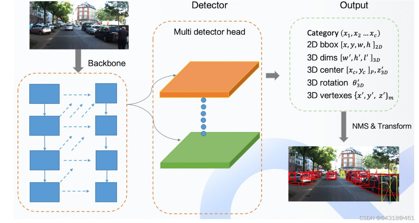
网络架构: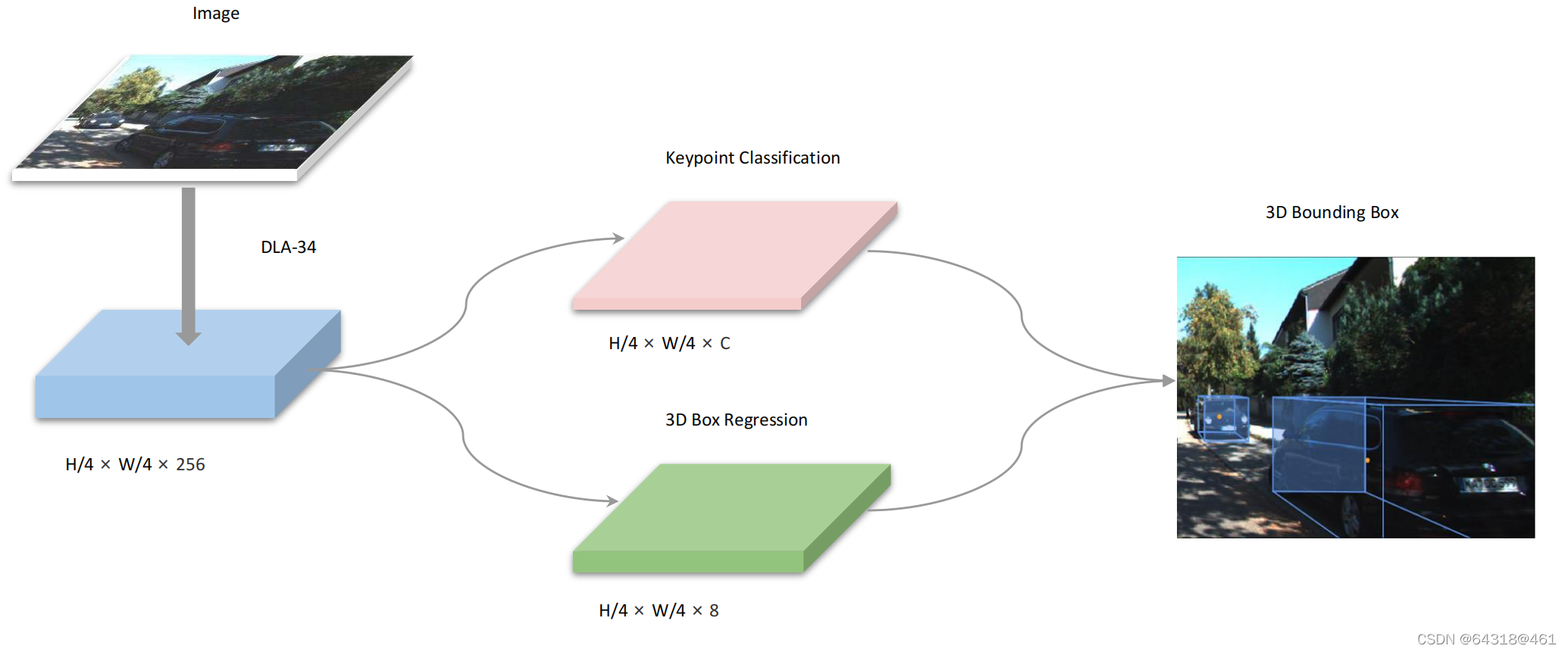
Figure 2. Network Structure of SMOKE. We leverage DLA-34 [41] to extract features from images. The size of the feature map is 1:4 due to downsampling by 4 of the original image. Two separate branches are attached to the feature map to perform keypoint classification(pink) and 3D box regression (green) jointly. The 3D bounding box is obtained by combining information from two branches.
【CC】Backbone是DLA-34,1/4的下采样;两个Header分别是keypoint 分类/3D-BB回归
Backbone
We use a hierarchical layer fusion network DLA-34 [41] as the backbone to extract features since it can aggregate information across different layers. Following the same structure as in [42], all the hierarchical aggregation connections are replaced by a Deformable Convolution Network (DCN). Compared with the original implementation, we replace all BatchNorm (BN) operation with GroupNorm (GN)
【CC】采用DLA-34进行不同层次的特征融合(类似FPD);网络参考了centPoint论文做了些改变:分层连接改成了DCN;BN改成了GN
Keypoint Branch
We define the keypoint estimation network similar to [42] such that each object is represented by one specific keypoint.
【CC】参考centPoint论文,一个keypoint代表一个object
Let[x y z]⊤ represent the 3D center of each object in the camera frame. The projection of 3D points to points [xc yc]⊤ on the image plane can be obtained with the camera intrinsic matrix K in a homogeneous form:
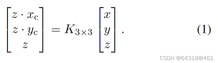
【CC】这是个经典的3D世界到相机平面投影的公式,K是相机内参,更具体可以参考《slam十四讲》
Each 3D box on the image is represented by 8 2D points[x_b,1∼8 y_b,1∼8]⊤ and the standard deviation is computed by the smallest 2D box with {x_b_min, y_b_min, x_b_max, y_b_max} that encircles the 3D box.
【CC】同样,将3D-BB的8个角点投影到相机平面得到8个2D的点,用[x_b,1∼8 y_b,1∼8]表示,该2D点在平面的标准差可以用 {x_b_min, y_b_min, x_b_max, y_b_max}来约束
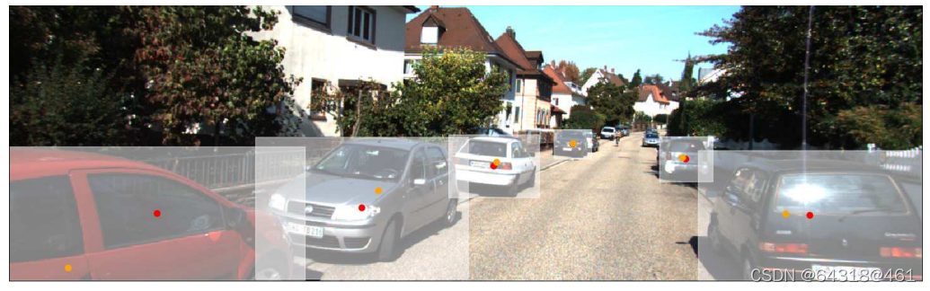
Figure 3. Visualization of difference between 2D center points (red) and 3D projected points (orange). Best viewed in color.
【CC】上图表明2D–BB中心点跟3D-BB中心点投射到2D后的点存在差异
Regression Branch:
The 3D information is encodedas an 8-tuple τ = [δz, δxc, δyc, δh, δw, δl, sin α, cos α]⊤. Here δz denotes the depth offset, δxc, δyc
is the discretization offset due to downsampling, δh, δw, δl denotes the residual dimensions, sin(α), cos(α) is the vectorial representation of the rotational angle α.
【CC】3D信息通过8元组表达[δz, δxc, δyc, δh, δw, δl, sin α, cos α]⊤, δz深度偏置(参看公式2),δxc, δyc下采样偏置(参看公式3),δh, δw, δl 变换后的表达(参看公式4),sin a/cos a 表示转角更进一步表达θ(参看公式5); 实际上这里的8元组通过变换可以得到原始的“3D-BB B表示为7维变量 (h, w, l, x, y, z, θ)”
For each object, its depth z can be recovered by pre-defined scale and shift parameters σz and µz as

【CC】深度z作为一个线性表达:σz为预定义的缩放因子,预定义的µz为偏置, δz为缩放因子下的偏置值
Given the object depth z, the location for each object in the camera frame can be recovered by using its discretized projected centroid [xc, yc]⊤ on the image plane and the downsampling offset [δxc, δyc]⊤:
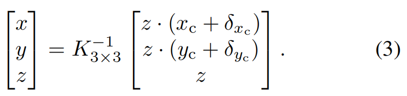
【CC】深度z由公式(2)给出,这里给出[xc, yc]⊤根据公式(3)计算得到[x, y ,z]; 实际上就是公式(1)的逆变换
In order to retrieve object dimensions[h w l]⊤, we use a pre-calculated category-wise average dimension[h¯ w¯ l¯]⊤ computed over the whole dataset. Each object dimension can be recovered by using the residual dimension offset [δh δw δl]⊤:
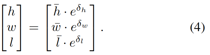
【CC】在整个数据集进行category得到h/w/l的缩放因子[h¯ w¯ l¯],然后dot上[δh δw δl]即得到3D空间的[h w l]
we choose to regress the observation angle α instead of the yaw rotation θ for each object. We further change the observation angle with respect to the object head αx, instead of the commonly used observation angle value αz, by simply adding π2.
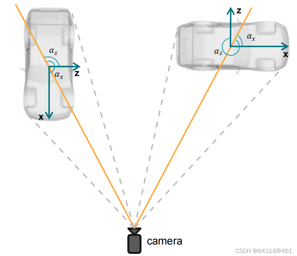
Figure 4. Relation of the observation angle αx and αz. αx is provided in KITTI, while αz is the value we choose to regress
【CC】αx vs αz有固定的几何关系-π2,而θ跟αz又有公式(5)的几何关系,因此可以用αx来表达θ; 在训练是回归αx即是在回归θ
Moreover, each α is encoded as the vector[sin(α) cos(α)]⊤. The yaw angle θ can be obtained by utilizing αz and the object location:
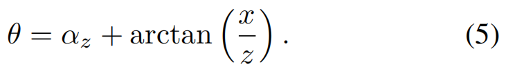
【CC】这里的αz可以用向量[sin(α) cos(α)]来表示,通过公式(5)计算得到θ
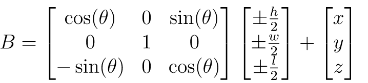
Finally, we can construct the 8 corners of the 3D bounding box in the camera frame by using the yaw rotation matrix Rθ, object dimensions[h w l]⊤ and location[x y z]⊤:
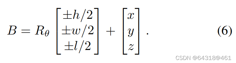
【CC】这里是最后我们要回归的3D BB的真实量,由公式(6)给出;这里明显是一个3D的量(就跟后面Lreg函数对上了)
Loss Function
- Keypoint Classification Loss
Let si,j be the predicted score at the heatmap location (i, j) and yi,j be the ground-truth value of each point assigned by Gaussian Kernel. Define y˘i,j and s˘i,j as:
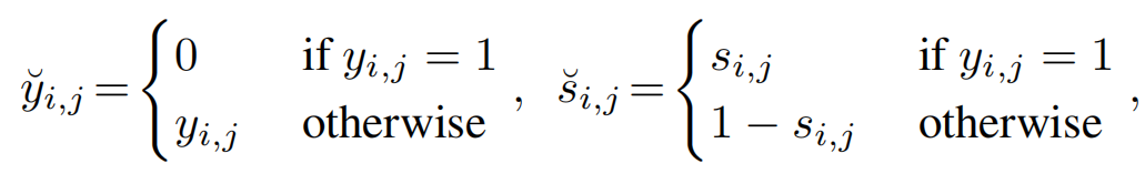
【CC】yi,j是高斯核函数关于每个点的真值函数值; si,j是热力图上每个点的预测得分
For simplicity, we only consider a single object class here. Then, the classification loss function is constructed as
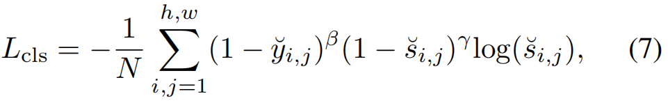
where γ and β are tunable hyper-parameters and N is the number of keypoints per image. The term (1 − yi,j )corresponds to penalty reduction for points around the groundtruth location.
【CC】整个公式(7)看起来像是一个CE函数;结合上面yi,j和si,j个人认为可以这么理解,y看做数据的真实分布, s看做网络对数据的预测分布;(1 − yi,j )惩罚项,理解为在真值yi,j附近点得分越高,会导致Lcls越高
- Regression Loss:
We regress the 8D tuple τ to construct the 3D bounding box for each object. We also add channelwise activation to the regressed parameters of dimension and orientation at each feature map location to preserve consistency. The activation functions for the dimension and the orientation are chosen to be the sigmoid function σ and the ℓ2 norm, respectively:
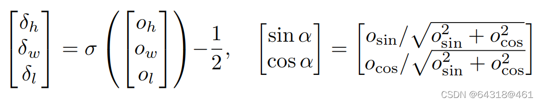
【CC】 8D tuple τ本身经过网络有激活函数处理分别是:sigmoid和ℓ2 norm,如上式
we define the 3D bounding box regression loss as the ℓ1 distance between the predicted transform Bˆ and the groundtruth B:
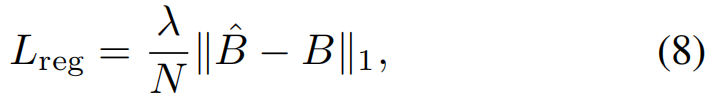
where λ is a scaling factor.
【CC】整个回归的Loss 就是一个简单的L1距离; 当然它是3Dim的参看公式(6)
In Eq. (3), we use the projected 3D groundtruth points on the image plane[xc yc]⊤ with the network predicted discretization offset[ˆδxc δˆyc]⊤
and depth zˆ to retrieve the location[xˆ yˆ zˆ]⊤ of each object. In Eq. (5), we use the groundtruth location[x y z]⊤ and the predicted observation angle ˆαz to construct the estimated yaw orientation θˆ.
【CC】这一段化其实就是Regression Branch开头介绍的各个量之间的转换关系,因为后面要归纳总的Loss func
The final loss function can be represented by:
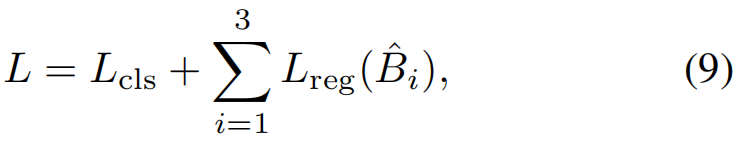
where i represents the number of groups we define in the 3D regression branch.
【CC】整个总的Loss Func参见公式(9),就是简单的线性相加
实现&Appollo扩展:
论文:https://github.com/lzccccc/SMOKE
Appollo7.0 其针对SMOKE的改进如下:
Here we mainly focus on the modifications based on SMOKE, more detail about SMOKE model please reference paper.
Deformable conv can not convert onnx or libtorch. Therefore, we modify the deformable convolution in the backbone to normal convolution, which will lead to the decline of mAP;
【CC】DCN不好实现,直接使用普通的Conv
Because the 3D center points of some obstacles may appear outside the image, these obstacles will be filtered out during training, resulting in missed detection. Therefore, we take the center point of 2D bounding boxes to represent the obstacle, and add a head prediction offset term to recover the 3D center point;
【CC】有肯能预测的3D中心点超出了图片导致Obj检测失败;这里还是采用的2D BB的中心点作为Obj的中心点,加了一个header去估计2D BB中心点关于3D BB中心点的offset
We add the head to predict the width and height of the 2D bounding box, and directly calculate the 2D bbox of the obstacle with 2D center;
【CC】加了header去估计2D BB的[w, h]
Using 2D bounding box and other 3D information, we use post-processing geometric constraints to optimize the predicted position information. Firstly, we use the 3D information predicted by the model to calculate the 3D bounding box of the obstacle, as shown in Formula 1. θ \theta θ represents the rotation of obstacle, h , w , l h,w,l h,w,l is the dimensions and x , y , z x,y,z x,y,z represent location。
Then, according to the corresponding relationship between the bounding boxes as the constraint condition, we optimized the position information of the obstacle as shown in formula 2.
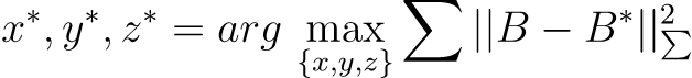
【CC】具体如何处理还得看APPOLO的代码; 大体思路先做B的估计(Formula 1),然后做二次型优化( formula 2)
The final network structure is shown below
重要参考文献:
[41] Fisher Yu, Dequan Wang, Evan Shelhamer, and Trevor Darrell. Deep layer aggregation. In CVPR, 2018.
[42] Xingyi Zhou, Dequan Wang, and Philipp Kr¨ahenb¨uhl. Objects as points. arXiv preprint arXiv:1904.07850, 2019.
https://github.com/ApolloAuto/apollo/blob/9f6bfa281999dc5f7592dea2ae870ee13e954ac3/modules/perception/camera/README.md