在使用stm32输出PWM波形时,笔者所用的stm32f103zet6中的高级定时器TIM1和TIM8可以输出互补的PWM波形,使用互补的PWM波常见与一些半桥电路和全桥电路控制中,使用MCU自带的高级时钟可以简便的解决互补PWM输出问题。
void TIM1_PWM1_DeadtimeInit ( u16 arr, u16 psc, u16 CCRx_val, u16 deadtime)
{ GPIO_InitTypeDef GPIO_InitSturcture; TIM_TimeBaseInitTypeDef TIM_TimeBaseInitStructure; TIM_OCInitTypeDef TIM_OCInitStructure; TIM_BDTRInitTypeDef TIM_BDTRInitStructure; RCC_APB2PeriphClockCmd ( RCC_APB2Periph_TIM1, ENABLE) ; RCC_APB2PeriphClockCmd ( RCC_APB2Periph_GPIOA| RCC_APB2Periph_GPIOB, ENABLE) ; GPIO_InitSturcture. GPIO_Pin = GPIO_Pin_8 ; GPIO_InitSturcture. GPIO_Mode = GPIO_Mode_AF_PP; GPIO_InitSturcture. GPIO_Speed = GPIO_Speed_50MHz; GPIO_Init ( GPIOA, & GPIO_InitSturcture) ; GPIO_InitSturcture. GPIO_Pin = GPIO_Pin_13 ; GPIO_InitSturcture. GPIO_Mode = GPIO_Mode_AF_PP; GPIO_InitSturcture. GPIO_Speed = GPIO_Speed_50MHz; GPIO_Init ( GPIOB, & GPIO_InitSturcture) ; TIM_TimeBaseInitStructure. TIM_Period = arr; TIM_TimeBaseInitStructure. TIM_Prescaler = psc; TIM_TimeBaseInitStructure. TIM_CounterMode = TIM_CounterMode_Up; TIM_TimeBaseInitStructure. TIM_ClockDivision = TIM_CKD_DIV1; TIM_TimeBaseInitStructure. TIM_RepetitionCounter = 0x00 ; TIM_TimeBaseInit ( TIM1, & TIM_TimeBaseInitStructure) ; TIM_OCInitStructure. TIM_OCMode = TIM_OCMode_PWM1; TIM_OCInitStructure. TIM_Pulse = CCRx_val; TIM_OCInitStructure. TIM_OCPolarity = TIM_OCPolarity_High; TIM_OCInitStructure. TIM_OCNPolarity = TIM_OCPolarity_High; TIM_OCInitStructure. TIM_OutputState = TIM_OutputState_Enable; TIM_OCInitStructure. TIM_OutputNState = TIM_OutputNState_Enable; TIM_OCInitStructure. TIM_OCIdleState = TIM_OCIdleState_Reset; TIM_OCInitStructure. TIM_OCNIdleState = TIM_OCNIdleState_Set; TIM_OC1Init ( TIM1, & TIM_OCInitStructure) ; TIM_OC1PreloadConfig ( TIM1, TIM_OCPreload_Enable) ; TIM_BDTRInitStructure. TIM_OSSRState = TIM_OSSRState_Enable; TIM_BDTRInitStructure. TIM_OSSIState = TIM_OSSIState_Enable; TIM_BDTRInitStructure. TIM_LOCKLevel = TIM_LOCKLevel_1; TIM_BDTRInitStructure. TIM_DeadTime = deadtime; TIM_BDTRInitStructure. TIM_Break = TIM_Break_Disable; TIM_BDTRInitStructure. TIM_BreakPolarity = TIM_BreakPolarity_Low; TIM_BDTRInitStructure. TIM_AutomaticOutput = TIM_AutomaticOutput_Enable; TIM_BDTRConfig ( TIM1, & TIM_BDTRInitStructure) ; TIM_ARRPreloadConfig ( TIM1, ENABLE) ; TIM_Cmd ( TIM1, ENABLE) ; TIM_CtrlPWMOutputs ( TIM1, ENABLE) ; TIM_DMACmd ( TIM1, TIM_DMA_Update, ENABLE) ;
}
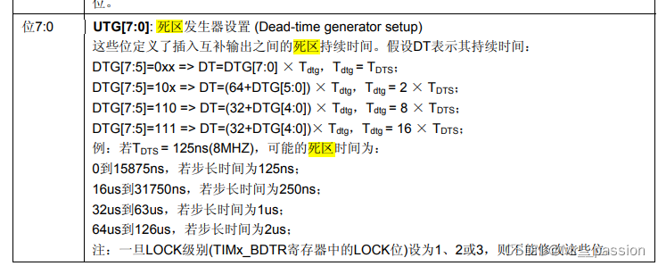
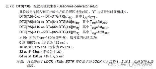
此处是笔者所初始化的一段互补PWM波形输出,通过此段初始化代码可以简单的看到互补PWM输出只需要通过相应的设计即可完成,不需要额外配置其他硬件电路,将两个3.3v的互补PWM接到相应的硬件电路与即可完成。 关于死区时间计算可以仔细研读一下stm32的手册